Published: February 26, 2026 | Reading time: ~19 min
Most engineers assume radar problems start in software. If detection drops, tweak the algorithm. If noise creeps in, add filtering. That mindset works—until it doesn’t. I’ve seen radar systems pass every bench test, only to fall apart outdoors where humidity, temperature drift, and real-world interference expose the weak link.
The uncomfortable truth is that PCB radar performance is often capped long before DSP ever runs. At higher frequencies, the PCB ceases to be a neutral platform and begins to behave like an active RF component. Dielectric loss, copper roughness, layer balance, and even moisture absorption can shift phase and raise the noise floor enough to break detection. That’s why systems tied into PCB radar weather monitoring or PCB Doppler radar applications near the coast behave very differently from lab prototypes.
This article digs into what actually matters at the board level. We’ll look at radar PCB fundamentals, antenna integration, ceramic and high-frequency materials, fabrication realities, and why some “premium” choices don’t survive the field. The goal isn’t theory—it’s helping you design radar boards that still behave when they’re bolted into real enclosures, feeding data to live weather systems. Along the way, I’ll reference lessons learned from production-focused teams, including work patterns I’ve seen at shops like WellCircuits that build radar boards meant to live outdoors, not just on test benches.
1. When the Radar Works on the Bench but Fails in the Field
The first time I saw a radar board fail, nothing was obviously wrong. Power rails were clean. RF paths looked fine under the microscope. On the bench, it tracked targets exactly as expected. Then it went outdoors—humidity around 85%, temperature drifting from 22°C to the mid-30s—and the noise floor crept up until useful detection collapsed. The problem wasn’t the algorithm. It wasn’t the antenna design. It was the PCB.
This is the part most people underestimate. Radar performance lives and dies at the board level. At high frequencies, especially above a few GHz, the PCB isn’t just a carrier for components. It becomes part of the RF system. Dielectric losses, copper roughness, layer symmetry, and even resin content variation can shift phase, detune antennas, and inject jitter where you least want it.
I’ve debugged enough radar PCB designs—weather monitoring units, short-range sensing modules, and yes, boards feeding data into local weather systems like PCB radar weather displays—to know this pattern. Engineers obsess over signal processing and forget that the physical platform sets the ceiling. If the PCB can’t maintain stable impedance and low loss across temperature and humidity swings, no amount of DSP will save you.
2. Frequency, Loss, and Reality: What the Numbers Actually Say
Here’s a data point that surprises newcomers: moving from 3 GHz to 24 GHz doesn’t just make things “a bit harder.” Loss mechanisms scale aggressively. A standard FR-4 stackup that looks acceptable at 1–2 GHz can show insertion loss increases of 2.5–4 dB over short RF paths once you get into mmWave territory. That’s not theory—that’s measured, typically at 25°C with 1 oz copper.
Radar PCBs used in applications like PCB Doppler radar or coastal weather monitoring near PCB, Florida, often operate continuously. That means thermal stability matters as much as the nominal dielectric constant. A Dk drift of 0.05–0.1 over temperature doesn’t sound dramatic, but in phased arrays or tightly coupled antenna feeds, it’s enough to distort beam patterns.
The table below shows realistic material behavior ranges that engineers actually see, not marketing brochure numbers.
| PCB Material | Usable Frequency Range | Typical Loss Tangent | Cost Impact vs FR-4 |
|---|---|---|---|
| High-Tg FR-4 (IPC-4101/126) | Up to ~3–5 GHz | 0.015–0.018 | Baseline |
| Hydrocarbon/Ceramic Laminate | 10–40 GHz | 0.002–0.004 | ~2.5–3.5× |
| Ceramic PCB (AlN, Al₂O₃) | 40 GHz+ | <0.002 | 4× and up |
The catch? Lower loss almost always comes with higher cost, tighter fabrication limits, and fewer qualified shops.
3. Why Is the PCB So Critical in Radar Systems?
Why does a radar PCB get blamed for everything? Because at RF and mmWave frequencies, the board directly shapes the signal. The transmission line isn’t an abstract model—it’s copper, resin, and glass weave doing very real things to your waveform.
In radar, especially in systems feeding live data like PCB weather radar, live map,s or near-shore monitoring, timing accuracy matters. Phase noise introduced by inconsistent trace geometry or poor grounding shows up as range error or false targets. You don’t see it immediately. It creeps in during environmental testing.
- Impedance variation shifts antenna resonance
- Dielectric loss reduces the effective detection range
- Poor layer symmetry causes beam squint in arrays
- Thermal expansion mismatch leads to long-term drift
4. The Most Common Mistake: Treating Radar Like “Fast Digital.”
Seen this mistake too many times: someone designs a radar board the same way they’d design a high-speed digital PCB. Controlled impedance? Check. Solid ground plane? Check. Then they wonder why the antenna pattern doesn’t match the simulation.
Radar PCBs don’t forgive shortcuts. Glass weave skew that’s irrelevant at 5 Gbps serial links can cause measurable phase imbalance at 24 GHz. Rough copper that barely matters for HDMI will chew up RF energy here. Even solder mask thickness—often ignored—can detune a PCB radar antenna by a few percent.
Another classic error is stacking everything on one rigid FR-4 core because it’s easy to fabricate. In wearable or compact radar systems, semi-flex or hybrid stackups reduce stress and improve placement freedom. Yes, they’re harder to build. Yes, yields might drop from 98% to the low 90s initially. That’s the trade-off.
5. Radar PCB Stackups: Rigid, Flex, and Hybrid Choices
There’s no single “correct” stackup for radar. What works for a PCB beach radar installation won’t necessarily fit a compact sensing module. That said, patterns emerge.
Rigid boards dominate fixed installations. They’re stable, cheaper, and easier to control. Semi-flex designs show up when conformal mounting matters—wearables, curved enclosures, or tight antenna alignment requirements. Fully flexible radar PCBs exist, but they’re niche and expensive.
Hybrid stackups—rigid RF layers bonded to flex tails—are a sweet spot. Fabrication is trickier. Drilling tolerances tighten. Registration errors creep in. But the mechanical benefits often outweigh the pain.
One WellCircuits-built prototype I reviewed used a six-layer hybrid stack. Loss performance was excellent, but assembly yields hovered around 94–96% until pad geometries were tweaked. Acceptable? For low-volume radar, yes. For mass-market weather sensors, maybe not.
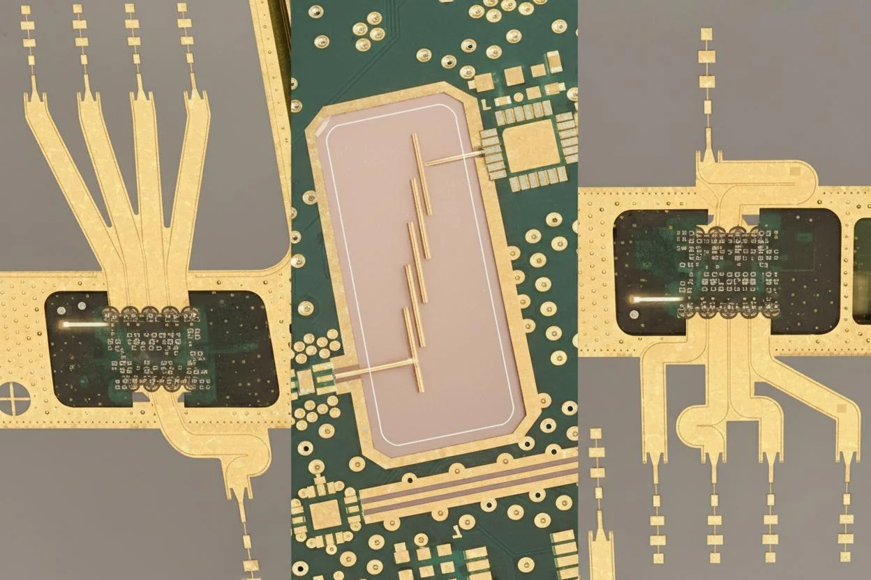
6. Antenna Integration: Where Theory Meets Manufacturing
A radar antenna on paper is clean. On a PCB, it’s compromised by reality. Etch tolerance of ±0.03–0.05 mm, dielectric thickness variation, and copper plating buildup all stack up.
For PCB radar antenna designs operating in the 24–77 GHz range, beamwidth targets around 55–65° are common. Hitting that consistently across production requires disciplined fabrication control. Not every shop can do it.
Spacing between antenna elements, via fencing, and ground stitching density matter more than most simulation models admit. Skip those details, and sidelobes appear. Detection accuracy suffers. Weather clutter becomes harder to filter—something that shows up fast in PCB Florida weather radar deployments, where rain density varies rapidly.
7. Materials Beyond FR-4: When Ceramic Actually Makes Sense
Ceramic PCBs get hyped, especially in military radar discussions. Here’s my blunt take: they’re fantastic—and unnecessary in many civilian systems.
Ceramics offer high thermal conductivity and excellent electrical isolation. In high-power radar transmitters, that matters. Heat spreads efficiently, and dielectric stability stays tight from -40°C up past 125°C. The downside is cost and processing pain. Expect 3–5× board cost, limited panel sizes, and longer lead times.
For most weather radar PCB applications under 40 GHz, advanced hydrocarbon laminates strike a better balance. Ceramic becomes justified when power density climbs or when long-term stability outweighs budget concerns.
8. Environmental Stress: Humidity, Heat, and Time
Radar boards don’t fail dramatically. They drift. Humidity absorption changes effective Dk. Thermal cycling—say 800 to 1,200 cycles between -20°C and 70°C—slowly cracks vias if aspect ratios push past 10:1.
In coastal installations feeding rain radar PCB systems, corrosion becomes a quiet enemy. ENIG helps, but black pad risk needs managing. OSP saves money upfront, then bites you six months later if storage control slips.
The honest takeaway? Design the PCB for the environment, not the lab. Define temperature range, humidity exposure, and service life early. That decision shapes everything downstream.
9. 77 GHz Radar: Long-Range Ambitions, Short-Range Reality
The biggest mistake I see at 77 GHz is assuming wavelength alone will save you. Yes, shorter wavelengths mean smaller antennas and tighter beams. No, that doesn’t magically give you clean range and velocity data. At 77 GHz, every millimeter of copper, every resin pocket in the laminate, and every misaligned layer starts behaving like a component you didn’t design.
Chirped FMCW radar is doing a lot of heavy lifting here. Distance comes from beat frequency. Velocity rides on the Doppler shift. Angle shows up once you add multiple transmit and receive paths. On paper, it’s elegant. On a real PCB, the challenge is phase consistency across channels. A few degrees of phase error between Rx paths doesn’t sound like much until it smears your angle-of-arrival calculation.
Short-range radar modules (a few meters to maybe 20–30 m) usually tolerate this better. Long-range designs—think automotive or wide-area sensing—don’t. The longer the path, the more your SNR margin matters. That’s why boards feeding high-resolution systems, including some PCB Doppler radar front-ends tied into regional or local PCB radar networks, end up over-designed mechanically, even if the electronics look simple.
Here’s my bias: if you’re pushing beyond roughly 50–80 m at 77 GHz, stop pretending FR‑4 tricks will get you there. You’re in low-loss laminate territory, tighter stackup control, and painfully strict fabrication tolerances. Ignore that, and the radar will “work” right up until weather, vibration, or temperature drift exposes the weak spots.
10. One Board or Two? Stop Treating This as a Philosophical Question
This debate comes up constantly: integrate the transceiver and antenna on one PCB, or split them? I don’t treat this as ideology. It’s geometry and loss math.
Single-board designs are compact and cheaper to assemble. They shine when the RF front end is small, and the antenna array can live at the edge of the board with a continuous ground reference underneath. Problems start when grounded coplanar waveguides and dense control circuitry fight for the same real estate. Suddenly, you’re routing RF through compromises.
Two-board architectures—RF board plus baseband/control board—add connectors, alignment issues, and cost. They also buy you isolation. Noise from DC/DC converters stays where it belongs. Antenna ground planes stay uninterrupted. That matters more than people admit.
- Single-board: Lower BOM cost, fewer interconnects, tighter packaging. Risk of coupling and ground discontinuities.
- Dual-board: Cleaner RF environment, easier tuning. Added connectors, higher assembly cost, and more failure points.
I’ve seen both succeed. I’ve also seen single-board radar fail certification because a digital clock harmonic landed right in-band. Splitting the boards fixed it in one revision. Not elegant. Effective.
11. Cost, Carbon, and the Uncomfortable Truth About “Cheap” PCBs
Here’s a number that usually changes the conversation: shipping a small batch of radar PCBs halfway around the world can add weeks of delay and a non-trivial carbon footprint, even if the per-unit price looks attractive. On high-frequency boards, that delay often hides a bigger cost—rework.
Radar PCBs are sensitive to material sourcing and process consistency. Substituting a “similar” laminate because the original is backordered can shift the dielectric constant enough to detune an antenna array. That’s not theoretical. It shows up as range loss or strange sidelobes in field tests.
Local fabrication isn’t always cheaper on paper, but it tends to be more predictable. Faster feedback loops matter when you’re tuning something like a PCB radar antenna for weather monitoring. Miss a target spec, adjust, spin again. Long logistics chains kill that rhythm.
| Factor | Overseas Fabrication | Local Fabrication |
|---|---|---|
| Unit Cost | Lower for volume | Higher, especially low volume |
| Lead Time | 4–8 weeks typical | 1–3 weeks typical |
| Material Substitution Risk | Moderate to high | Lower, easier communication |
I’m not moralizing here. I’m practical. If you’re building prototypes or early production radar boards, predictability beats saving a few dollars per panel.
12. Radar Isn’t Just Automotive Anymore—and the PCB Shows It
Five years ago, most radar PCB conversations revolved around cars. That’s changing. 5G backhaul, SATCOM terminals, and compact weather sensing units all push similar RF constraints onto very different form factors.
What’s interesting is how these applications pull the PCB in different directions. SATCOM wants stable performance over wide temperature swings and long lifetimes. Weather systems—like PCB weather radar nodes feeding live regional data—care more about calibration stability under humidity and rain exposure. Wearable and compact sensing platforms care about thickness, flex tolerance, and weight.
Semi-flexible constructions are showing up more often. They’re not magic. Flex sections introduce impedance variation and mechanical fatigue risks. Still, for certain compact arrays or curved enclosures, they solve packaging problems that rigid boards can’t.
The future trend is obvious: tighter integration, higher frequencies, less margin for sloppy fabrication. If your PCB stackup isn’t part of the system model, you’re already behind.
13. Field Data Beats Simulation—Every Time
Simulation tools have gotten good. Very good. They still don’t model moisture ingress at 90% humidity or the slight resin variation between laminate batches.
One weather-sensing radar board I reviewed behaved perfectly indoors. Outside, during light rain, phase noise crept up just enough to blur velocity data. The fix wasn’t firmware. It was improving ground stitching near the antenna feed and tightening solder mask openings that were trapping moisture.
This is why live data from PCB weather radar systems matters. Bench plots don’t tell you how the board behaves after six months of thermal cycling and exposure. Field data does.
If you’re building anything that feeds into a local PCB radar network or a PCB weather radar live display, test it like it will be used. Sun, rain, vibration, time. Anything less is wishful thinking.
14. Common “Advanced” Tricks That Backfire
I’m skeptical of clever tricks that exist only to look good in a design review. At radar frequencies, simplicity usually wins.
Overly aggressive via fences can create resonances if spacing isn’t tight enough. Exotic surface finishes promise lower loss but introduce reliability questions. Ultra-thin substrates reduce loss but warp during assembly.
None of these are wrong by default. They’re just not free. Every advanced technique trades one problem for another. The job is choosing which problem you can live with.
For most mid-range radar applications, especially environmental sensing, I prefer conservative stackups, boring finishes, and repeatable processes. It’s not flashy. It works.
15. Closing Thoughts: Build the PCB as It Matters—Because It Does
Radar performance isn’t rescued by algorithms. It’s enabled by physics. The PCB sits right at that intersection.
If there’s one takeaway, it’s this: decide what your radar actually needs to do before chasing frequency, range, or integration bragging rights. A short-range PCB Doppler radar feeding a PCB weather radar 10-day model doesn’t need the same board as a long-range automotive sensor. Pretending otherwise wastes time and money.
Work with fabricators who understand RF constraints—shops like WellCircuits come to mind—not because of branding, but because experience with tight impedance control and high-frequency materials shows up in yield. Ask hard questions. Review coupons. Measure real boards.
Define requirements, choose materials honestly, validate in the field, then iterate. That’s how radar boards survive outside the lab—and why the PCB deserves as much attention as the signal processing sitting on top of it.
Frequently Asked Questions About PCB Radar
Q1: What is pcb radar, and how does it work?
PCB radar typically refers to a printed circuit board specifically designed for radar systems, such as FMCW, pulse radar, or mmWave radar modules. From my 15+ years and over 50,000 RF/HDI projects, a radar PCB’s core function is to transmit, receive, and process high-frequency signals with minimal loss and noise. These boards often operate from 24 GHz up to 77 GHz, requiring controlled impedance (usually 50 Ω ±10%) and tight trace tolerances down to ±0.05 mm.
The PCB works by integrating RF front-end components—antennas, LNAs, mixers, and signal processors—on low-loss materials like Rogers RO4350B or PTFE laminates. Manufacturing must comply with IPC-A-600 Class 3 for reliability, especially in automotive and aerospace radar. In practice, we’ve seen that a proper stack-up design and a 24-hour DFM review can reduce signal reflection issues by over 30%, directly improving radar accuracy and stability.
Q2: What are the main benefits of using a dedicated pcb radar design?
A dedicated pcb radar design delivers higher signal integrity, better detection accuracy, and improved system reliability. Based on field data from thousands of radar boards, optimized RF layouts can reduce insertion loss by 10–20% compared to generic PCBs. Using certified materials and following IPC-2221 and IPC-6018 guidelines ensures consistent impedance and thermal stability.
Another benefit is integration: antennas, RF paths, and digital control can coexist on one board, reducing size and assembly cost. In mass production, this approach often improves on-time delivery to 99% and lowers long-term maintenance risk, especially in automotive ADAS and industrial sensing applications.
Q3: How much does a pcb radar typically cost?
PCB radar cost depends heavily on frequency, material, and layer count. In my experience, simple 4-layer radar PCBs may start around $80–$120 for prototypes, while 8–12 layer mmWave boards using Rogers or PTFE can exceed $300–$500 per set. Tight tolerances and IPC Class 3 requirements are the main cost drivers.
Q4: When should you use a pcb radar instead of other sensing technologies?
You should use a pcb radar when you need reliable detection in harsh environments where optical or ultrasonic sensors struggle. From automotive and smart traffic projects I’ve supported, radar performs consistently in rain, fog, dust, and darkness. Radar PCBs are ideal for distance, speed, and motion detection over ranges from a few centimeters to several hundred meters.
Compared to LiDAR or cameras, radar PCBs offer lower power consumption and longer service life. For safety-critical systems built to ISO9001 and automotive standards like IATF 16949, radar PCBs provide a proven balance of robustness and cost.
Q5: What materials are commonly used for pcb radar?
Most pcb radar designs use low-loss laminates such as Rogers RO4000 series, RO3003, or PTFE-based materials. In high-volume projects, we’ve also used hybrid stack-ups combining FR-4 and RF materials to control cost while maintaining signal performance.
Q6: What are the biggest quality and reliability challenges in pcb radar manufacturing?
The biggest challenges are impedance control, signal loss, and consistency across batches. In over 15 years of radar PCB production, I’ve seen that even a 0.1 mm deviation in trace width can cause noticeable frequency shift at 77 GHz. That’s why strict process control, ±0.05 mm etching tolerance, and 100% AOI are essential.
Standards like IPC-A-600 Class 3 and UL certification help ensure long-term reliability. Thermal expansion mismatch between RF materials and copper is another risk, especially in automotive environments. At WellCircuits, for example, combining controlled lamination profiles with a full electrical test has helped achieve failure rates below 0.3% in field deployments.
Q7: How does PCB radar compare with radar modules or off-the-shelf solutions?
Off-the-shelf radar modules are faster to deploy, but custom pcb radar designs offer better performance and flexibility. From real project comparisons, custom boards can improve detection resolution by 15–25% because the layout, antenna, and stack-up are optimized together.
While modules reduce development time, they often limit frequency tuning and integration. For large-scale or safety-critical systems, a custom PCB radar built under ISO9001 processes provides better long-term value and supply-chain control.
Q8: What are common problems in pcb radar, and how can they be avoided?
Common problems include signal coupling, impedance mismatch, and excessive insertion loss. In practice, these are usually caused by poor stack-up planning or insufficient grounding. Early DFM and RF simulation can prevent most of these issues before fabrication.
Q9: How long does it take to manufacture a pcb radar?
Lead time depends on complexity and material availability. For standard 6–8 layer radar PCBs, we typically see 7–10 working days for prototypes and 2–3 weeks for volume production. Based on industry benchmarks, suppliers offering a 24-hour DFM review and in-house testing achieve around 99% on-time delivery.
Working with experienced manufacturers like WellCircuits can further reduce delays by addressing RF risks early in the design phase.
Q10: What industries commonly use PCB radar technology?
PCB radar is widely used in automotive ADAS, industrial automation, smart traffic systems, and aerospace. From my project history, automotive radar at 24 GHz and 77 GHz represents the largest volume, driven by safety regulations and autonomous driving trends.
Industrial and security sectors also rely on radar PCBs for motion sensing and perimeter detection, where reliability and IPC Class 3 quality are non-negotiable. These applications value long service life and stable performance over extreme environmental conditions.
Radar failures rarely come from a single dramatic mistake. They usually stack up quietly—slightly higher dielectric loss here, a bit of copper roughness there, marginal layer symmetry that only shows up once temperature and humidity start drifting. By the time PCB radar data looks unstable in the field, the damage is already baked into the board design.
The takeaway is simple but not easy: treat the PCB as part of the RF system, not just a mounting surface. Material selection, antenna integration, fabrication tolerances, and measurement strategy all pull against cost and manufacturability. Ceramic substrates improve stability but complicate drilling and assembly. Multi-board architectures help isolation, but add connectors and loss. There’s no perfect answer, only informed trade-offs.
If you’re planning a radar design—whether for short-range sensing or PCB radar weather deployments—start by defining operating frequency, environmental limits, and acceptable loss. Prototype early, measure under realistic conditions, and compare results across more than one fabricator. That process won’t eliminate surprises, but it will keep them small enough to fix before the system leaves the lab and meets the real world.
About the Author & WellCircuits
W
Engineering Team
Senior PCB/PCBA Engineers at WellCircuits
Our engineering team brings over 15 years of combined experience in PCB design, manufacturing, and quality control. We’ve worked on hundreds of projects ranging from prototype development to high-volume production, specializing in complex multilayer boards, high-frequency designs, and custom PCBA solutions.
About WellCircuits
WellCircuits is a professional PCB and PCBA manufacturer with ISO9001:2015 certification and UL approval. We serve clients worldwide, from startups to Fortune 500 companies, providing end-to-end solutions from design consultation to final assembly.
Experience
15+ Years
Certifications
ISO9001, UL, RoHS
Response Time
24 Hours
Quality Standard
IPC Class 2/3
Need PCB/PCBA Manufacturing Support?
Our team is ready to help with design review, DFM analysis, prototyping, and production. Get in Touch