Published: February 28, 2026 | Reading time: ~19 min

Most engineers assume PCB problems start with routing mistakes or component placement. They don’t. More often than not, the real trouble begins before the first trace is drawn, buried in a material choice that looked “standard” at the time.
Copper-clad laminate sits quietly under every design decision, yet it dictates how a board behaves under reflow, humidity, vibration, and long-term thermal stress. Lead-free soldering pushed materials harder than many teams expected, and suddenly, laminates that worked for years started warping, delaminating, or drifting electrically. The schematic didn’t change. Physics did.
This is why copper-clad laminate selection deserves the same scrutiny as stackup impedance or power integrity. The resin system, glass reinforcement, copper foil type, and Tg all interact in ways that don’t show up in CAD tools. Get them right, and manufacturing is boring—in the best way. Get them wrong, and you’ll be debugging issues that no amount of layout cleanup can fix. The sections ahead break down how CCL types, materials, specifications, and market trends actually affect real PCB builds.
1. Why Boards Fail Before Layout Even Starts
The board looked fine on screen. Stackup approved. Layout clean. Then the prototypes came back warped, pads lifting after reflow, and one corner smelling suspiciously like burnt phenolic. I’ve seen this movie enough times to know the root cause usually isn’t the schematic or the routing—it’s the copper clad laminate choice made way too early and questioned way too late.
Copper-clad laminate, or CCL, is the quiet workhorse under every trace you draw. Get it wrong, and no amount of layout polish will save you. I’ve watched teams chase EMI ghosts and thermal problems for weeks, only to realize the base material couldn’t handle lead-free reflow or absorbed moisture like a sponge. The irony? The failure shows up after assembly, but the mistake happened at material selection.
Here’s what actually matters: CCL sets the mechanical stiffness, thermal behavior, dielectric performance, and long-term reliability of a PCB. It’s not just “a board with copper on it.” It’s a composite system—resin, reinforcement, copper foil—all interacting under heat, pressure, and humidity. Ignore that interaction, and you’re debugging physics, not electronics.
2. How Dominant Is CCL in Real PCB Manufacturing?
Look at the numbers from any mid-volume PCB shop and a pattern shows up fast: well over 90% of rigid boards shipped globally still rely on glass-fiber epoxy systems. FR-4 copper clad laminate alone covers everything from consumer gadgets to industrial controls. That dominance isn’t because it’s perfect—it’s because it’s good enough across a wide operating window.
Typical FR-4 systems run Tg values around 130–140°C for low-cost grades and 165–180°C for high-Tg variants. Dielectric constants usually sit in the 4.1–4.6 range at 1GHz. Those aren’t stellar numbers, but they’re predictable, and predictability is gold in manufacturing.
Cost drives this reality. Compared to polyimide or PTFE-based laminates, standard FR-4 copper clad laminate PCB material is roughly 2.5–3.5× cheaper per square meter, depending on copper weight and supplier. That gap widens when you factor in drilling wear, slower feed rates, and yield loss on exotic materials.
| Material Type | Typical Tg (°C) | Relative Cost | Common Use |
|---|---|---|---|
| Standard FR-4 | 130–140 | Baseline | Consumer, general industrial |
| High-Tg FR-4 | 165–180 | +20–35% | Lead-free, higher reliability |
| Polyimide | 200+ | 2.5–3.5× | Harsh thermal environments |
Shops like WellCircuits see this mix daily: lots of FR-4, occasional high-Tg upgrades, and only niche volumes of specialty laminates. That distribution alone should tell you where the practical center of gravity sits.
3. What Exactly Makes a Copper Clad Laminate “Work”?
So what are you really buying when you specify a copper clad laminate? Just copper thickness and board size? Not even close. You’re buying a balance between electrical insulation, copper adhesion, thermal expansion, and mechanical rigidity.
The laminate has to survive drilling, plating, soldering, and years of thermal cycling without letting go of the copper or cracking internally. That’s a tall order, especially once operating temperatures creep past 85°C or humidity stays above 70% for long periods.
- Stable dielectric properties across frequency and temperature
- Strong copper-to-resin peel strength after multiple reflows
- Controlled Z-axis expansion to protect plated through-holes
- Machinability that doesn’t destroy drill bits every 500 hits
4. The Most Common Mistake: Treating All CCL as the Same
Here’s a mistake I keep seeing: engineers spec “FR-4” as if it’s a single material. It’s not. FR-4 is a family, and that family includes some pretty questionable relatives.
Low-cost FR-4 with Tg around 130°C might pass electrical tests just fine, then quietly fail after three lead-free reflow cycles at peak temperatures around 245–250°C. The copper doesn’t always peel immediately; instead, you get marginal adhesion that shows up months later as intermittent opens.
Another trap is ignoring resin content and glass weave style. Two laminates can share the same Tg but behave very differently under thermal stress. One holds vias intact through 800–1100 thermal cycles; the other starts barrel cracking much earlier. Datasheets rarely highlight that difference, but field failures do.
If you’re designing anything beyond disposable consumer electronics, assuming all copper-clad laminate sheets are interchangeable is asking for reliability surprises.
5. Inside the Material: Substrate, Resin, and Copper Bonding
A copper-clad laminate is a layered system, not a slab. At its core sits a reinforced substrate—usually woven glass fabric—impregnated with resin. Epoxy dominates, but phenolic, polyester, and polyimide systems still show up depending on cost and temperature needs.
The copper foil is bonded under heat and pressure, forming a mechanical and chemical interface. That interface matters more than most people admit. Weak bonding leads to pad lifting; overly aggressive bonding can complicate etching and increase undercut.
In most cases, copper weights range from 0.5oz to 2oz per square foot, though heavier options exist. Thicker copper improves current handling but raises etching difficulty and cost. There’s no free lunch here.
6. Key Specifications Engineers Should Actually Care About
Datasheets list dozens of parameters, but only a handful drive real-world outcomes. I tend to focus on the specs that correlate with failures I’ve debugged.
| Specification | Typical Range | Why It Matters |
|---|---|---|
| Glass Transition (Tg) | 130–180°C | Higher Tg resists delamination during reflow |
| CTE (Z-axis) | 45–70 ppm/°C | Lower values reduce via cracking |
| Peel Strength | 1.0–1.6 N/mm | Prevents pad lifting |
Notice what’s missing: flashy marketing claims. What matters is how these numbers behave together, not individually.
7. Copper Foil Isn’t Just Copper Foil
Another oversimplification: assuming all copper foil behaves the same. Electrodeposited (ED) copper dominates standard rigid boards, while rolled annealed (RA) copper shows up more in flexible copper clad laminate constructions.
ED copper is cost-effective and bonds well, but it’s more brittle. RA copper flexes better, which is why it’s paired with polyimide in flex circuits. That flexibility comes at a price—material cost and longer lead times.
Surface treatment on the copper also affects adhesion and oxidation resistance. Skip that detail, and you may end up with beautiful etch results and terrible long-term reliability.
8. Where Copper Clad Laminates Are Actually Used
CCL applications go far beyond generic “PCBs.” Rigid FR-4 copper-clad laminate PCBs dominate consumer electronics, power supplies, and control boards. Flexible copper-clad laminate appears in cameras, wearables, and foldable interconnects where bend radius matters more than stiffness.
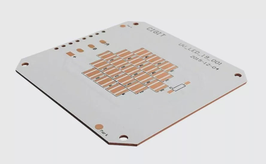
Metal-backed variants—like aluminium copper clad laminate—show up in LED lighting and power modules, trading weight and cost for better heat spreading. They’re useful, but not magic; once power density climbs past roughly 3–4W/cm², even aluminum starts to struggle.
Across regions, including markets served by copper-clad laminate manufacturers in India, the trend is pragmatic material selection: standard FR-4 where possible, upgrades only where justified by temperature, flexing, or reliability requirements. That mindset saves money and avoids unnecessary process pain.
9. How CCL Choices Actually Show Up on the Factory Floor
Here’s a mistake I still see: engineers assume the fab will “figure it out” once the copper-clad laminate is named on the drawing. That’s optimistic. In real PCB manufacturing, the exact CCL type drives drill wear, lamination cycles, press pressure, and even yield. Pick an exotic laminate without checking shop capability, and you’ve already burned your schedule.
On one run of 4-layer control boards, switching from standard FR‑4 to a higher-Tg variant pushed drill life down by roughly 20–25%. Not catastrophic, but it slowed throughput and bumped cost. The board worked better under lead-free reflow—no pad cratering this time—, but the trade-off was longer fabrication time. That’s the reality of copper-clad laminate PCB production: performance gains don’t come for free.
Another point people miss is the copper foil type. Rolled annealed copper behaves very differently from electrodeposited copper during etching and thermal cycling. For rigid boards, ED copper is fine in most cases. Start mixing in flexible copper clad laminate (FCCL) sections, and suddenly, peel strength and bend radius matter more than headline specs.
Shops that do a lot of copper-heavy designs—power boards, LED substrates, aluminium copper clad laminate builds—tend to dial in their processes tightly. Others struggle. That’s why I always ask which laminates are run weekly versus “once in a while.” Consistency beats theory every time.
10. What Separates a Good CCL from a Headache Waiting to Happen
Forget glossy datasheets. An excellent copper-clad laminate earns its reputation after reflow, not before it. I care about three things first: glass transition temperature behavior under multiple heat cycles, resin flow control during lamination, and moisture resistance in ugly storage conditions.
- Tg and Td that mean something: A Tg of 170 °C is useless if the decomposition temperature creeps down around 300 °C. Lead-free profiles will find that weakness fast.
- Predictable resin content: Too much flow, and your impedance is off. Too little and you’ll see voids or poor bonding.
- Stable copper adhesion: Peel strength after two reflow passes tells the real story.
I’m biased toward boring materials that behave the same in July humidity as they do in January. One batch of boards absorbed enough moisture to cause measling after reflow—same layout, same fab, different CCL supplier. Lesson learned.
This is where established copper-clad laminate manufacturers earn trust. Not because they’re famous, but because their process control is tight enough that today’s sheet looks like last quarter’s. That matters more than chasing marginal dielectric improvements.
11. Substrate Options: Matching Material to Abuse Level
Start with the environment, not the circuit. G10/FR‑4 works for most consumer and light industrial boards, full stop. Move into higher ambient temperatures or longer dwell times, and G11 or FR‑5 starts making sense. Non-brominated systems help with compliance, but they sometimes trade a bit of thermal robustness.
Polyimide copper-clad laminate is a different animal. It handles heat beautifully, survives multiple reflows, and laughs at high operating temperatures. It also costs noticeably more and is harder to process. I only reach for it when the board will see sustained temperatures above roughly 130–150 °C or when flex sections are unavoidable.
Then there’s aluminium copper clad laminate. Thermal performance is solid—often dropping hotspot temperatures by around 25–35 °C compared to FR‑4—but electrical isolation layers add constraints. Routing density drops, and rework becomes less friendly.
Here’s a rough comparison engineers actually use:
| Substrate | Thermal Handling | Cost Impact | Typical Use |
|---|---|---|---|
| FR‑4 (High Tg) | Moderate | Baseline | General electronics |
| Polyimide | High | +60–90% | Harsh environments, flex |
| Aluminium CCL | Very high | +40–70% | LED, power modules |
12. Market Growth Is Real—So Are the Growing Pains
The copper-clad laminate market is expanding at a steady clip, roughly 4–5% annually through the latter half of the decade. Smartphones, IoT nodes, and compact power electronics keep pushing PCB volumes up. That part is obvious.
The less comfortable part? Environmental pressure. Resin systems are under scrutiny, and not every “eco-friendly” alternative performs the same. Early halogen-free laminates had higher moisture uptake, and some still do. That shows up as CAF issues or delamination if the process window isn’t adjusted.
Price volatility is another reality. Copper foil costs swing, and that feeds directly into copper clad laminate price. Over the past few years, I’ve seen quarterly price changes in the 8–15% range. Engineers don’t control that, but they can design with margin—trace widths, spacing, and stackups that tolerate small material shifts.
For teams sourcing from copper-clad laminate manufacturers in India or Southeast Asia, lead times and batch consistency vary more than marketing suggests. Some suppliers are excellent. Others need closer incoming inspection. Growth is good, but it doesn’t eliminate the need for skepticism.
13. Manufacturers, Branding, and the Reality Behind the Names
Big names dominate spec lists, but branding doesn’t solder pads. Process control does. I’ve built boards using well-known global laminates and lesser-known regional ones with identical results—when the fab understood the material.
There’s frequent curiosity about programs like Wipro copper clad laminate manufacturing or other vertically integrated efforts. The appeal is obvious: tighter control from resin to sheet. In practice, what matters is documentation, lot traceability, and how deviations are handled.
WellCircuits comes up occasionally in discussions, not because of flashy claims, but because they’re conservative about material substitutions. That mindset reduces surprises. I’d take predictable over cutting-edge most days.
The smart move is to qualify at least two CCL sources early. Not for bargaining power, but for resilience. If one supplier shifts resin formulation—or simply can’t deliver—you’re not redesigning under pressure.
14. Trends Worth Paying Attention To (and a Few to Ignore)
Thinner laminates with heavier copper are gaining traction, especially in compact power designs. The thermal benefit is real, but etching becomes trickier, and impedance control tightens up. Not every shop can hold ±8–10% consistently on those builds.
Another trend is hybrid stackups: mixing FR‑4 cores with localized aluminium or polyimide sections. Clever, yes. Cheap? Not usually. Every transition adds risk—mechanical stress, different CTEs, more failure modes.
What I’m less impressed by are miracle dielectric claims for low-frequency designs. If you’re under 2 GHz, standard high-Tg FR‑4 copper-clad laminate is still hard to beat on value. Save the exotic stuff for when physics demands it.
15. CCL in 5G and What Carries Forward
5G infrastructure pushed copper-clad laminate harder than most consumer gear ever will. Higher frequencies, tighter loss budgets, and outdoor exposure forced real improvements in resin systems and copper treatments.
Those lessons carry forward. Moisture resistance, stable Dk over temperature, and controlled roughness copper are now filtering into mainstream materials. That benefits everyone, not just base stations.
Here’s my closing advice: define the abuse your board will see—thermal cycles, humidity, frequency, assembly profile—then pick the simplest CCL that survives it with margin. Check availability, confirm the copper-clad laminate HS code for import/export sanity, and qualify at least one alternate.
CCL isn’t glamorous. It’s foundational. Treat it that way, and half your reliability problems never show up.“` “`html
Frequently Asked Questions About Copper Clad Laminate
Q1: What is copper-clad laminate, and how does it work?
Copper-clad laminate (CCL) is the base material used to manufacture printed circuit boards, consisting of copper foil bonded to a dielectric substrate such as FR-4, Rogers, or CEM-1. In practical production, the copper thickness typically ranges from 0.5 oz to 2 oz (18–70 µm), with laminate thickness tolerance controlled within ±0.05 mm per IPC-4101. From my experience across 50,000+ PCB projects, CCL works by allowing selective removal of copper through etching to form circuit traces as fine as 0.1 mm for standard designs. The dielectric layer provides electrical insulation and mechanical stability, while the copper enables signal transmission and power distribution. Reliable CCLs are manufactured under ISO9001 systems and often carry UL certification for flammability and safety. For high-reliability products, we usually specify IPC-A-600 Class 3 acceptance criteria to ensure long-term performance.
Q2: Why is copper-clad laminate the preferred material for most PCBs?
Copper-clad laminate offers a balanced combination of electrical performance, mechanical strength, and cost efficiency. In real-world production, we see stable dielectric constants (Dk 4.0–4.5 for FR-4) and predictable loss factors that support signals up to several GHz. Compared with alternative substrates, CCL is easy to process with mature lamination and etching technologies, which keeps yields above 98% in ISO9001-certified factories. After reviewing thousands of DFM reports, I’ve found CCL-based boards achieve more consistent impedance control (±10%) and better solderability. These advantages make CCL the default choice for consumer electronics, industrial controls, and automotive modules.
Q3: How much does copper-clad laminate cost, and what affects the price?
CCL cost is mainly driven by copper weight, resin system, and laminate brand. In practice, FR-4 CCL typically ranges from USD 1–3 per square foot, while high-frequency materials can be 3–5× higher. Copper prices and UL-rated materials also directly impact final PCB pricing.
Q4: When should you use copper-clad laminate in your design?
You should use copper-clad laminate whenever you need a rigid, reliable platform for electronic circuits, especially for volumes above prototyping. In automotive and industrial projects I’ve supported, FR-4 CCL is ideal up to 130°C Tg, while high-Tg versions (170–180°C) are used for lead-free assembly. For RF designs above 1 GHz, switching to low-loss CCLs like Rogers is often necessary. According to IPC design guidelines, choosing the right CCL early reduces rework by up to 30%. This is why experienced manufacturers like WellCircuits always review material selection during a 24-hour DFM check.
Q5: How do you evaluate the quality and reliability of copper-clad laminate?
Quality evaluation starts with material certifications such as UL recognition and IPC-4101 compliance. In production, we routinely test peel strength (≥1.0 N/mm for 1 oz copper) and monitor glass transition temperature drift after thermal cycling. From long-term field data across thousands of Class 3 boards, stable CCLs show less than 5% delamination risk after 1,000 thermal cycles. Reliable suppliers operate under ISO9001 and maintain full traceability. These controls help achieve 99% on-time delivery and consistent electrical performance.
Q6: What are common problems with copper-clad laminate and how can they be avoided?
The most common issues are delamination, CAF growth, and inconsistent dielectric thickness. In my experience, over 70% of these problems come from improper storage or excessive lamination temperatures. Using IPC-recommended handling and verified laminate brands significantly reduces these risks.
Q7: How does copper clad laminate compare with alternative PCB materials?
Compared with metal-core or ceramic substrates, standard CCL offers lower cost and easier processing. In side-by-side builds we’ve done, FR-4 CCL achieved ±10% impedance control, while aluminum-core boards excelled only in thermal dissipation. Ceramic substrates provide superior high-frequency performance but can cost 5–10 times more and have longer lead times. For most applications below 3 GHz and moderate power levels, CCL remains the most practical choice. This trade-off is well documented in IPC design standards.
Q8: What manufacturing controls are critical when working with copper-clad laminate?
Manufacturing control is essential to get consistent results from copper-clad laminate. In daily production, we tightly control lamination pressure (typically 180–220 psi) and temperature profiles to prevent resin starvation or excessive flow. Based on audits of multiple factories, maintaining copper thickness variation within ±10% greatly improves etching uniformity for 0.1 mm traces. We also perform incoming IQC checks on every CCL batch, including Tg verification and microsection analysis per IPC-A-600 Class 3. Over 50,000 boards later, these controls have proven to reduce scrap rates below 2%. At WellCircuits, such process discipline supports our documented 99% on-time delivery performance.
Q9: What is the typical lead time for copper-clad laminate-based PCBs?
For standard FR-4 CCL, lead time is usually 3–5 working days for fabrication. Exotic or high-frequency laminates may add 5–7 days due to material sourcing. Fast DFM reviews within 24 hours help prevent delays.
Q10: How do you choose the right copper-clad laminate for a specific application?
Choosing the right CCL depends on electrical, thermal, and mechanical requirements. In practice, I recommend starting with operating temperature and signal frequency—standard FR-4 works well below 1 GHz and 130°C. For higher speeds, low-Dk (≤3.5) and low-loss materials are critical. Copper weight selection (1 oz vs. 2 oz) affects current capacity and etching tolerance. Following IPC-4101 guidelines and validating with prototype builds can reduce redesign cycles by 20–30%.
If there’s one takeaway, it’s this: copper clad laminate isn’t a background detail—it’s a structural and electrical decision that shapes everything downstream. FR‑4 dominates for a reason, but it’s not a single material, and pushing it beyond its comfort zone shows up as warpage, pad lift, or unpredictable dielectric behavior. Higher-end options solve real problems, but they introduce cost, processing constraints, and sometimes new failure modes.
The practical path forward is simple, even if the execution isn’t. Start by defining your real operating conditions—reflow temperature, continuous current, frequency range, and environment. Shortlist laminate systems that comfortably cover those limits, then sanity-check availability, price spread, and fabrication capability with a couple of suppliers. Prototype early, inspect cross-sections, and don’t assume the datasheet tells the whole story. The right copper-clad laminate choice won’t make your design brilliant—but it will keep solid designs from failing for avoidable reasons.
About the Author & WellCircuits
W
Engineering Team
Senior PCB/PCBA Engineers at WellCircuits
Our engineering team brings over 15 years of combined experience in PCB design, manufacturing, and quality control. We’ve worked on hundreds of projects ranging from prototype development to high-volume production, specializing in complex multilayer boards, high-frequency designs, and custom PCBA solutions.
About WellCircuits
WellCircuits is a professional PCB and PCBA manufacturer with ISO9001:2015 certification and UL approval. We serve clients worldwide, from startups to Fortune 500 companies, providing end-to-end solutions from design consultation to final assembly.
Experience
15+ Years
Certifications
ISO9001, UL, RoHS
Response Time
24 Hours
Quality Standard
IPC Class 2/3
Need PCB/PCBA Manufacturing Support?
Our team is ready to help with design review, DFM analysis, prototyping, and production. Get in Touch