Published: January 30, 2026 | Reading time: ~18 min
Why do some boards fail thermal testing while identical designs pass? Same schematic, same layout, same assembly line—yet one batch survives, and the other comes back warped or cracked. More often than people admit, the answer isn’t routing or soldering. It’s buried in the laminate.
Copper-clad laminate doesn’t get much respect. It’s treated as a line item on a BOM, usually defaulting to “FR‑4, 1.6 mm” without much discussion. That works—until it doesn’t. Lead‑free reflow temperatures, higher power density, tighter tolerances, and longer field life have pushed standard materials harder than they were ever meant to go. Suddenly, Tg, resin chemistry, copper foil type, and glass weave start showing up as real failure drivers.
This article takes copper-clad laminate out of the background and puts it where it belongs: as a core engineering decision. We’ll break down how CCL actually works, the real differences among material types, where common assumptions fall apart, and why trends like 5G and higher-speed digital are driving change. If you’ve ever wondered why two “identical” boards behave very differently, the answer usually starts here.
1. Why Boards Fail Before They Ever Ship
A board came back from thermal testing once—nothing exotic, just a control PCB running around 70–75°C ambient: same schematic, same layout, same assembly line. Half the batch passed. The other half warped just enough to crack solder joints near the connectors. The root cause wasn’t the layout. It wasn’t an assembly. It was the copper-clad laminate choice.
This is the part most people gloss over. Copper clad laminate (CCL) sits quietly at the bottom of the PCB stack-up, and because it’s “standard,” engineers assume it’s interchangeable. It isn’t. The resin system, glass content, copper foil type, and even how that copper is bonded—all of it affects reliability long before anyone starts arguing about components.
In most cases, CCL is a reinforced insulating substrate—glass fiber, paper, or polymer film—impregnated with resin and laminated with copper foil on one or both sides. That copper gets etched into traces later, but at this stage, it’s the mechanical and thermal backbone of the board. Get this wrong, and no amount of clever routing will save you.
I’ve debugged enough warped, brittle, or delaminated boards to say this plainly: CCL selection isn’t a paperwork task. It’s an engineering decision, and it shows up fast when the board sees heat, humidity, or mechanical stress.
2. How Dominant Is Copper Clad Laminate in PCB Manufacturing?
Look at the numbers and the picture gets clear. Well over 90% of rigid PCBs shipped globally are still built on some variant of glass-reinforced epoxy copper clad laminate—mostly FR‑4. Despite all the hype around exotic substrates, that hasn’t changed much in the last decade.
Typical FR‑4 copper-clad laminate thickness sits around 1.6 mm, with copper weights from 0.5 oz to 2 oz per side. That combination covers a huge range of consumer and industrial electronics. Cost is the big driver here: compared to specialty laminates, FR‑4 usually lands at roughly 1× baseline cost, while high-frequency or polyimide-based options can climb to 2.5–3.5× depending on volume and region.
Flexible copper clad laminate (FCCL) is a smaller slice of the market, but it’s growing steadily—especially in wearables, cameras, and compact interconnects. These are typically polyimide films with very thin copper layers, sometimes under 18 µm, which opens the door to ultra-fine patterning but brings its own handling headaches.
| CCL Category | Typical Thickness | Relative Cost | Common Use |
|---|---|---|---|
| FR‑4 Copper Clad Laminate | 0.8–2.0 mm | Baseline (1×) | Consumer, industrial control |
| Flexible Copper Clad Laminate | 25–125 µm | 2–3× | Wearables, cameras, flex cables |
| Metal-based CCL | 1.0–1.6 mm | 2–4× | LED, power electronics |
Suppliers like WellCircuits see this mix daily—high-volume FR‑4, with smaller but demanding runs of flex and metal-core boards where material control matters more than raw price.
3. What Exactly Makes Up a Copper Clad Laminate?
So what are you actually buying when you specify copper-clad laminate? Just copper and fiberglass? Not quite.
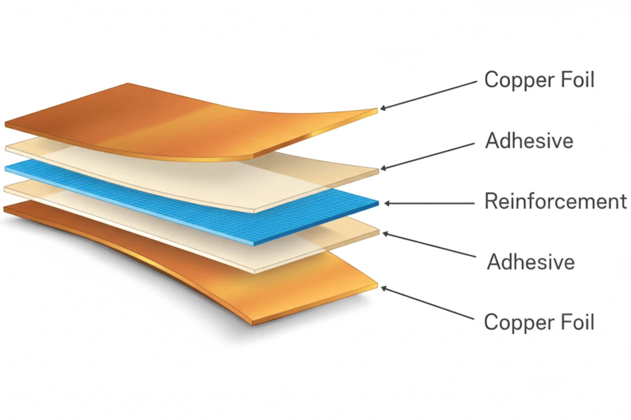
At a minimum, you’re dealing with three interacting elements: the copper foil, the resin system, and the reinforcement (glass cloth, paper, or film). Change any one of these and electrical, thermal, and mechanical behavior shifts—sometimes subtly, sometimes dramatically.
- Copper foil: Usually electrodeposited or rolled. Thickness affects current capacity and etching tolerance.
- Resin: Epoxy, phenolic, polyester, or polyimide. Drives Tg, moisture absorption, and heat resistance.
- Reinforcement: Glass cloth for rigidity, paper for cost, polymer film for flexibility.
This combination is pressed under heat and pressure into a stable laminate. Stability is the goal, but stability depends heavily on how well these layers bond and expand together under temperature swings.
4. The Most Common CCL Mistake I Keep Seeing
Here’s the mistake: treating all FR‑4 copper-clad laminate as identical. Same label, same performance—right? That assumption breaks boards.
FR‑4 is a family, not a single material. Tg can be anywhere from roughly 130°C to over 170°C. Glass weave styles vary. Resin formulations change between manufacturers. Two laminates, both called “FR‑4,” can behave very differently during lead-free reflow or thermal cycling.
I’ve seen designs pass prototyping and then fail in production because the laminate source changed. The layout didn’t move a micron. The copper didn’t get thicker. Only the resin system shifted, and suddenly delamination showed up around vias after 6–8 reflow cycles.
If your board sees sustained heat above 90°C or repeated reflow, low-Tg FR‑4 is a gamble. It might work. It might not. That’s not where you want uncertainty.
5. CCL Types: More Than Just FR‑4
Classification gets messy fast, but in practice, CCL types fall into a few buckets that engineers actually care about.
Paper-based laminates (FR‑1, FR‑2, XPC) are cheap and easy to punch, but they absorb moisture and hate heat. They’re fine for low-cost consumer gear that never sees high temperatures. Glass-fiber laminates—FR‑4 and FR‑5—are the workhorse, balancing cost, strength, and thermal performance.
Then there are composite materials like CEM‑1 and CEM‑3. These mix paper and glass to shave cost while keeping some mechanical stability. They’re common in appliances, but not something I’d push into harsh environments.
Specialty CCLs include aluminium copper clad laminate for thermal spreading and ceramic-based options for high power density. These solve real problems, but they add weight, machining complexity, and cost—often 2–4× compared to standard FR‑4.
6. Inside the Copper Clad Laminate Manufacturing Process
Most failures trace back to bonding, so it’s worth understanding how CCL is actually made.
The process usually starts with copper foil—either electrodeposited (ED) or rolled annealed (RA). ED foil is cheaper and common in rigid boards. RA foil bends better, which is why it shows up in flexible copper-clad laminate.
Resin-impregnated reinforcement (prepreg) is stacked with copper sheets and pressed under controlled heat and pressure. Temperature ramps, dwell time, and pressure profiles matter. Too aggressive and resin starvation show up. Too gentle, and the outer peel strength suffers.
Adhesiveless FCCL—often polyimide-based—skips traditional adhesive layers entirely. Copper is formed directly onto the film, producing a flatter interface and enabling very fine traces. The trade-off? Tighter process windows and higher material cost.
7. Copper Foil: Thin Metal, Big Consequences
Copper looks simple on a datasheet. It isn’t.
Foil thickness typically ranges from about 12 µm to 70 µm. Thicker copper carries more current but becomes harder to etch cleanly, especially below 0.15 mm trace widths. Thin copper enables fine lines but heats up faster under load.
Surface treatment matters too. Roughened copper bonds better to resin, but increases signal loss at higher frequencies. Smoother foils help with impedance control but can peel if lamination isn’t dialed in.
There’s no universal “best” copper foil—only the one that fits your electrical, thermal, and manufacturing constraints.
8. Where Copper Clad Laminate Actually Gets Used
CCL ends up everywhere, but not all applications stress it the same way.
Televisions, routers, and power adapters mostly live happy lives on FR‑4 copper-clad laminate. Temperatures stay moderate, volumes are high, and cost pressure dominates. Move into automotive modules or industrial drives, and the picture changes—higher ambient temperatures, vibration, and longer lifetimes expose weaknesses fast.
Flexible copper-clad laminate shows up in camera modules, foldable connections, and compact consumer devices where space matters more than rigidity. Aluminium copper clad laminate earns its keep in LED lighting and power conversion, spreading heat where FR‑4 struggles.
Understanding the environment—heat, humidity, mechanical stress—is the real starting point. Application first, laminate second. Do it the other way around, and you’ll be chasing failures later.
9. PCB Manufacturing Reality: Not All CCL Behaves the Same on the Line
The mistake I keep seeing is treating copper-clad laminate like a passive ingredient. It’s not. On the fabrication floor, different CCL types behave very differently once you start drilling, plating, and laminating multilayer stacks.
FR-4 copper-clad laminate is forgiving. Drill wear is predictable, smear control is manageable, and most shops have the lamination profiles dialed in. Switch to polyimide or flexible copper clad laminate (FCCL), and suddenly drill speeds drop, desmear chemistry gets touchy, and yield can slide a few points if the process window isn’t tight.
I’ve watched a batch of mixed CCL panels—same design, different material lots—produce hole wall quality that varied just enough to fail IPC-A-600 Class 2 on annular ring integrity. Nothing dramatic. Just micro-voids that only showed up after thermal stress. The board “worked” until it didn’t.
This is where manufacturer capability matters more than datasheets. Some PCB shops tune their copper-clad laminate manufacturing process around a narrow material set. Ask them to run aluminum copper clad laminate or high-Tg polyimide without prep, and you’re rolling the dice. Even experienced suppliers like WellCircuits will tell you up front which CCL families their process windows actually like—and which ones need extra controls, time, or cost.
10. What Actually Makes a Copper Clad Laminate “Good”?
Forget glossy brochures. An excellent CCL earns its keep under heat, humidity, and mechanical stress—not in a spec table.
- Resin system stability: Tg matters, but resin decomposition temperature (Td) matters more once you hit lead-free reflow. Below ~300°C Td, long-term reliability starts slipping.
- Copper peel strength consistency: Not the headline value—the spread. Wide variation across panels is a red flag.
- Glass weave control: Poor weave shows up as CAF failures or impedance drift in high-speed designs.
- Moisture absorption: FR-4 around 0.1–0.2% is manageable. Polyimide can be higher and needs baking discipline.
One power board I reviewed looked fine electrically but failed after a few months in a humid enclosure. Root cause wasn’t the layout. The laminate absorbed just enough moisture that repeated heating cycles weakened the copper-resin bond near vias.
“Good” CCL isn’t about maximum specs. It’s about repeatability. I’d take a slightly lower Tg material that behaves the same every lot over a high-end laminate with wild process variation.
11. How Copper Clad Laminates Are Classified (And Why It’s Messy)
If you expect a clean taxonomy, you’ll be disappointed. CCL classification mixes material science, application history, and regional standards.
Broadly, you’ll hear categories like paper-based, glass epoxy (FR series), composite, metal-backed, and flexible. Within FR-4 alone, IPC-4101 lists dozens of slash sheets. Same name, different chemistry.
Then there’s copper type: electrodeposited (ED) versus rolled annealed (RA). ED dominates rigid boards. RA shows up in flexible copper-clad laminate because it survives bending without cracking. That choice alone changes cost, etching behavior, and current-carrying limits.
Add regional sourcing, and things get even fuzzier. Copper-clad laminate manufacturers in India often follow the same IPC framework, but resin formulations and glass sourcing can differ from Japanese or Taiwanese suppliers. Electrically similar on paper. Mechanically? Not always.
Classification helps narrow options. It doesn’t replace validation. Anyone who claims otherwise hasn’t chased intermittent failures at 2 a.m.
12. Product Groups: Rigid, Flexible, and Metal-Backed—Choose Your Compromise
Every CCL product group solves one problem while creating another. There’s no free lunch here.
Rigid laminates (FR-4 and high-Tg variants) handle most designs up to a few GHz and moderate thermal loads. Cheap, available, predictable. Their weakness shows up under sustained heat or tight bending radii.
Flexible copper clad laminate—polyimide with RA copper—shines where motion or tight packaging matters. The trade-off is cost and processing sensitivity. Over-etch it or over-bake it, and yields drop fast.
Metal-backed laminates, especially aluminum copper-clad laminate, spread heat well. LED boards love them. The catch is weight, grounding complexity, and limited multilayer options.
| CCL Group | Main Strength | Typical Trade-Off |
|---|---|---|
| FR-4 Rigid | Low cost, easy processing | Thermal limits around 130–170°C Tg |
| Flexible (FCCL) | Bend endurance | 2–3× material cost, tighter process window |
| Aluminum-backed | Heat spreading | Limited layer count, heavier |
13. Ordering CCL: Where Designs Get Quietly Locked In
By the time someone says “start the copper clad order,” most design decisions are already frozen. That’s risky.
Lead time alone can swing from a week to six, depending on laminate type and thickness. Copper weight above 2 oz? Expect fewer suppliers. Non-standard glass styles? Expect longer queues. Copper-clad laminate price also isn’t linear—small spec changes can bump cost by 15–25%.
This is also where compliance sneaks in. Export documentation often asks for copper-clad laminate HS code (typically 7410-series). Miss that detail and shipments stall for days.
My bias: involve the fabricator early. Even a short DFM check can flag material constraints that aren’t obvious in CAD. It’s cheaper to swap laminate on paper than after prototypes fail.
14. Where CCL Is Headed (And What’s Mostly Hype)
Data tells the story. Over the last few years, demand has shifted toward higher Tg FR-4, low-loss laminates, and thinner cores. That tracks with faster interfaces and denser packaging.
Some trends deserve skepticism. Ultra-low Dk materials marketed for sub-2GHz designs rarely justify their cost. I’ve seen high-Tg FR-4 perform within a few percent electrically at a fraction of the price.
What’s real is process-driven improvement: better copper surface treatments, tighter resin content control, and more consistent glass weave. These don’t make headlines, but they reduce scrap and improve long-term reliability.
Flexible and hybrid rigid-flex CCL growth is also real, pushed by wearables and compact industrial gear. Just don’t underestimate the learning curve. Early adopters often pay in yield before they pay in invoices.
15. 5G, High Frequency, and the Limits of Traditional CCL
Here’s the uncomfortable truth: 5G didn’t break FR-4 overnight. It exposed its edges.
At higher frequencies, dielectric loss and glass weave effects start to matter. Standard FR-4 copper-clad laminate can still work for parts of the signal chain, but stack-ups get complicated fast. Mixing low-loss cores with FR-4 prepregs introduces CTE mismatches that show up during thermal cycling.
Low-loss laminates solve signal integrity problems while creating mechanical ones. They’re softer, sometimes brittle, and less tolerant of rough handling. I’ve seen corner cracks appear during depaneling—not during operation.
The path forward isn’t abandoning FR-4. It’s smarter hybrid designs, tighter impedance control, and honest testing. Define frequency, loss budget, and thermal stress first. Then pick the laminate that survives all three—not just the one with the best marketing slide.
That mindset saves boards, schedules, and reputations. And in this industry, that’s what actually matters.
Frequently Asked Questions About Copper Clad Laminate
Q1: What is copper-clad laminate, and how does it work?
Copper-clad laminate (CCL) is the base material used to manufacture the most rigid and flexible printed circuit boards. From hands-on experience across 50,000+ PCB projects, CCL typically consists of a resin system (such as FR-4 epoxy) reinforced with fiberglass and bonded to one or two layers of copper foil, commonly 0.5 oz to 2 oz (17–70 μm). The copper layer is later patterned through imaging and etching to form circuit traces as fine as 0.1 mm. CCL works by providing both mechanical support and electrical conductivity, while the dielectric layer ensures controlled impedance and insulation. High-quality CCL must meet IPC-4101 specifications and is often UL certified for flammability (UL 94 V-0). In Class 3 designs, laminate thickness tolerance is typically held within ±0.05 mm to ensure reliability.
Q2: Why is copper-clad laminate widely used in PCB manufacturing?
Copper-clad laminate offers an excellent balance of electrical performance, mechanical strength, and cost, which is why it dominates over 90% of rigid PCB applications. In our production experience, FR-4-based CCL provides stable dielectric constants (Dk 4.2–4.6) suitable for most digital and power designs. It supports multilayer stacking, fine-pitch components, and IPC-A-600 Class 2 or Class 3 requirements. Compared to alternative substrates, CCL is widely available, UL-listed, and compatible with ISO9001-certified fabrication processes. For most consumer, industrial, and automotive electronics, it delivers predictable performance with minimal risk.
Q3: How much does copper-clad laminate cost?
CCL cost varies by material type, thickness, and copper weight. In real production, standard FR-4 CCL typically adds USD $0.20–$0.60 per PCB for low-layer designs. High-Tg or halogen-free laminates can cost 20–40% more. Prices fluctuate with global copper markets, but reliable suppliers maintain stable lead times and 99% on-time delivery.
Q4: When should I choose high-Tg or special copper-clad laminate?
High-Tg or specialty CCL should be used when boards face elevated temperatures, thermal cycling, or high reliability requirements. From experience in automotive and power electronics projects, Tg ≥170°C laminates significantly reduce delamination risk during lead-free reflow at 245–260°C. These materials also offer better Z-axis expansion control, critical for 6-layer and above designs. Standards such as IPC-4101/126 or /129 are commonly specified for such applications. While costs are higher, the long-term reliability gains usually outweigh the initial material premium.
Q5: How does copper-clad laminate affect signal integrity?
CCL directly influences impedance, signal loss, and crosstalk. In high-speed designs we’ve built, consistent dielectric thickness and Dk variation within ±0.1 are essential for controlled impedance lines (±10%). Low-loss laminates can reduce insertion loss by 20–30% compared to standard FR-4 at 5–10 GHz. Copper roughness also matters; smoother copper improves high-frequency performance. Choosing IPC-qualified materials and validating stackups during a 24-hour DFM review helps avoid costly redesigns.
Q6: What are common quality issues with copper-clad laminate?
The most common issues are delamination, resin voids, and inconsistent copper thickness. In our audits, these problems often trace back to non-UL-listed materials or poor storage conditions. Reputable manufacturers test CCL per IPC-4101 and incoming IQC standards to ensure long-term reliability.
Q7: How is copper-clad laminate manufactured and qualified?
CCL manufacturing involves impregnating fiberglass with resin (prepreg), stacking it with copper foil, and curing it under high heat and pressure. Based on factory evaluations we’ve done over 15 years, process control during lamination is critical to maintain thickness tolerance within ±0.03–0.05 mm. After production, laminates undergo peel strength, dielectric breakdown, and thermal stress testing. UL certification, IPC-4101 compliance, and ISO9001 quality systems are baseline requirements for serious PCB suppliers. At WellCircuits, we only approve laminate vendors that pass long-term thermal cycling and solder float tests, ensuring stable performance in mass production.
Q8: Copper-clad laminate vs aluminum substrate – what’s the difference?
CCL is designed for electrical routing and multilayer flexibility, while aluminum substrates focus on heat dissipation. In LED and power projects we’ve supported, aluminum boards reduce thermal resistance but limit trace density and layer count. Standard CCL supports fine traces, vias, and complex stackups but relies on copper planes and thermal vias for heat management. The choice depends on whether electrical complexity or thermal performance is the priority.
Q9: Is copper-clad laminate suitable for high-reliability electronics?
Yes, when the right grade is selected. For aerospace or medical projects, we specify IPC-A-600 Class 3 laminates with proven Tg and Td values. Field data shows that properly qualified CCL can exceed 10+ years of service life under harsh conditions.
Q10: How can I ensure I choose the right copper-clad laminate supplier?
Start by checking certifications: UL, IPC-4101 compliance, and ISO9001 are non-negotiable. From sourcing experience, suppliers offering full traceability, lot-level testing, and fast DFM feedback reduce risk significantly. Ask for material datasheets and thermal reliability reports. Manufacturers like WellCircuits also perform incoming laminate verification to ensure consistency before production, which directly impacts yield and delivery reliability.
Copper-clad laminate isn’t glamorous, but it quietly determines whether a board stays flat, survives reflow, and holds together after thousands of thermal cycles. FR‑4 still dominates for good reasons—cost, availability, and process maturity—but it’s not a single material, and treating it like one causes problems. Resin systems, Tg, copper foil treatment, and reinforcement all pull in different directions, and pushing one parameter often exposes another weakness.
The practical takeaway is simple: match the laminate to the actual stress your board will see, not the stress you hope it won’t. Start by defining operating temperature, reflow profile, layer count, and expected lifespan. Compare copper-clad laminate options from multiple suppliers, prototype with the same material you plan to ship, and pay attention to early signs like warpage or pad cratering. No laminate choice is perfect, but informed trade-offs beat surprises after production every time.
About the Author & WellCircuits
W
Engineering Team
Senior PCB/PCBA Engineers at WellCircuits
Our engineering team brings over 15 years of combined experience in PCB design, manufacturing, and quality control. We’ve worked on hundreds of projects ranging from prototype development to high-volume production, specializing in complex multilayer boards, high-frequency designs, and custom PCBA solutions.
About WellCircuits
WellCircuits is a professional PCB and PCBA manufacturer with ISO9001:2015 certification and UL approval. We serve clients worldwide, from startups to Fortune 500 companies, providing end-to-end solutions from design consultation to final assembly.
Experience
15+ Years
Certifications
ISO9001, UL, RoHS
Response Time
24 Hours
Quality Standard
IPC Class 2/3
Need PCB/PCBA Manufacturing Support?
Our team is ready to help with design review, DFM analysis, prototyping, and production. Get in Touch