What are PCBs
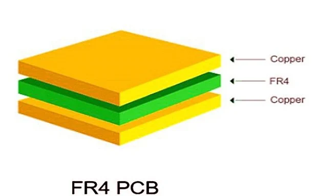
Printed circuit boards (PCBs) consist of conductive and insulating layers that are laminated together with copper traces connecting the various components of an electronic circuit. The standard practice for printed circuit boards (PCBs) involves using soldering to affix electronic components, which ensures proper electrical connections and structural support. Modern electronics rely heavily on these components, which appear in every product from consumer electronics like smartphones to industrial machines.
For substrate materials, PCB material is divided into two parts:
FR-4: serves as the standard substrate material for PCBs through its composition of glass-reinforced epoxy laminate sheeting.
Metal-core PCBs utilize aluminum or copper substrates to provide superior thermal management capabilities for high-power electronic applications.
Importance of Material Selection in PCB Design
The choice of PCB material affects board performance significantly because it determines reliability along with the board’s electrical and environmental capabilities.
Overall circuit performance depends on how the selected material affects power and signal loss, interconnect impedance, thermal management, and copper surface roughness.
Tailored PCB materials are essential to preserve signal integrity across different applications, especially for high-speed and high-frequency designs. In these scenarios, the dielectric constant (Dk) and loss tangent (Df) assume critical importance because they control how signals propagate and get attenuated.
PCB materials in consumer electronics and automotive engineering need to accommodate miniaturization while maintaining stable performance in demanding environments such as high temperatures and voltage fluctuations, as well as mechanical pressure.
Overview of PCB Materials
Printed circuit board substrates serve as the basic structural layers and are mainly made from insulating materials like fiberglass-reinforced epoxy (FR-4) or high-performance plastics. The substrates fulfill vital functions by providing mechanical stability along with electrical insulation and dependable pathways for circuit connections.
The choice of material for PCB substrates relies on application demands, which encompass electrical performance standards, thermal robustness requirements, and cost considerations because these aspects determine both the board’s performance and its durability.
Multiple essential properties guide engineers during the evaluation process for PCB materials.
The dielectric constant (Dk) and dissipation factor (Df) control signal integrity specifically in high-frequency circuit designs.
Power electronics require effective heat dissipation, which depends on thermal conductivity.
The Coefficient of thermal expansion (CTE) plays a vital role in maintaining dimensional stability when PCBs face thermal stress.
The thermal conductivity of standard PCB laminates like FR-4 ranges from 0.3 to 0.5 W/m·K, which necessitates additional thermal management methods such as copper planes and thermal vias when used in high-power applications.
The glass transition temperature (Tg) represents a vital parameter because it defines when the substrate changes from being rigid to becoming pliable. The glass transition temperature (Tg) of standard FR-4 sits between 130–140°C, which establishes its performance boundary in high-temperature conditions.
FR-4: The Standard Choice
PCB manufacturers adopted FR-4 as their standard substrate because it combines excellent electrical insulation qualities with minimal water absorption. Both consumer and industrial electronics widely adopt this material because it offers exceptional performance at a low cost.
The designation “4” in FR-4 represents its NEMA grading classification that details its electrical and thermal properties. The woven fiberglass reinforcement gives this composite material its mechanical strength while also providing excellent electrical insulation.
FR-4 exhibits thermal stability through its low coefficient of thermal expansion (CTE). This feature maintains dimensional stability through temperature changes, which enables its use in applications that demand consistent performance when exposed to thermal stress.
Rogers High-Frequency Laminates
Rogers high-frequency laminates outperform conventional FR-4 materials in RF and microwave PCB applications by providing superior performance benefits. Their precisely controlled dielectric constants and exceptionally low loss tangents distinguish these laminates, which are essential for maintaining signal integrity in high-frequency designs.
The hydrocarbon ceramic laminate Rogers RO4350B serves as an ideal illustration by offering exceptional electrical consistency. The material keeps its dielectric constant at 3.48 steady throughout the frequency spectrum of 100 MHz to 10 GHz while maintaining an ultra-low dissipation factor of 0.002 at 1 GHz.
Rogers’ unique blend of polymer and ceramic materials forms the foundation of these superior properties. The distinct composition achieves the best combination of electrical functionality along with thermal regulation features. Microwave and millimeter wave circuits prefer Rogers laminates because they consistently demonstrate proven reliability along with superior thermal stability and mechanical robustness.
Polyimide: High-Temperature Solutions
Polyimide laminates excel as high-performance materials that preserve their structural strength at temperatures above 300°C. Their excellent thermal stability makes them perfect for demanding aerospace, automotive, and industrial electronics applications where extreme heat resistance is essential.
Polyimide PCB substrates not only withstand high temperatures but also provide a distinctive blend of features.
- Outstanding chemical resistance
- Exceptional flexibility
- Lightweight characteristics
- Superior electrical insulation
Designers need to be aware that polyimide materials tend to absorb more moisture than standard FR-4, which requires pre-baking to remove moisture before it can affect performance.
DuPont’s Kapton series represents the best in polyimide films because they maintain mechanical strength under extreme conditions and provide improved thermal conductivity. Polyimide retains its position as the preferred material for flexible PCBs in mission-critical applications because of its excellent electrical insulation properties and environmental durability, combined with other key features.
PTFE: Implications for High-Frequency Applications
High-frequency and microwave PCBs now prefer PTFE (Polytetrafluoroethylene) because of its exceptional electrical attributes. PTFE achieves excellent signal integrity in high-performance RF applications due to its ultra-low dielectric constant between 2.1 and 2.3, combined with its minimal loss tangent. RF power amplifiers, along with microwave filters and next-generation 5G antenna systems, benefit from these properties because they require minimized dielectric attenuation.
PTFE demonstrates exceptional thermal stability by maintaining its performance at continuous operating temperatures of up to 250°C. The material’s inherent chemical inertness, combined with its thermoplastic properties, produces thermal resilience. PTFE requires specific reinforcement materials because its soft and flexible mechanical properties make it unsuitable for PCB substrates without added dimensional stability.
Surface preparation stands out as a crucial step in the manufacturing process of PTFE PCBs. The material displays a slick surface and chemical resistance which benefits numerous applications but creates adhesion difficulties when applying copper plating and solder masks. Specialized surface treatments during fabrication become essential to guarantee dependable layer bonding and accurate circuit patterning.
Ceramic Substrates: Advanced Applications
Ceramic PCB substrates such as alumina (Al₂O₃) and aluminum nitride (AlN) deliver superior performance compared to traditional organic laminates regarding thermal management and electrical insulation. Applications requiring high-power density designs depend on these inorganic materials for their unparalleled ability to dissipate heat efficiently.
Ceramic substrates stand out due to their superior thermal conductivity, which exceeds that of standard FR-4 materials by 10 to 20 times. This property makes them particularly valuable in:
- High-power electronics
- Extreme-temperature environments
- Mission-critical systems (aerospace, military, medical)
The production of ceramic PCBs utilizes direct bonded copper or thick-film printing methods to produce strong interconnects that endure extreme operating environments. Despite their high cost and design complexity constraints, ceramic substrates deliver essential benefits for applications such as:
- High-brightness LED arrays
- RF/microwave power amplifiers
- Automotive power modules
Ceramics’ low coefficient of thermal expansion (CTE) aligns well with semiconductor materials, an advantage that many people fail to recognize. This specific feature enables better performance through thermal cycles, which helps prevent failures caused by stress in harsh environments.
Key Properties of PCB Materials
The dielectric constants of PCB materials range from 2.5 to 4.5, which have direct effects on signal velocity and intertrace capacitance. Liquid Crystal Polymer (LCP) outperforms polyimide in high-frequency applications due to its better dielectric loss characteristics and lower moisture absorption ability.
The choice of substrate materials depends heavily upon thermal management needs, with Aluminum Nitride offering better thermal conductivity than regular materials. Applications require specific material properties, which FR4 delivers through its economical rigidity and polyimide delivers through its flexible insulation capabilities.
The dissipation factor (Df) of materials maintains its importance for determining power losses at high frequencies, which differ with varying operational frequencies. The parameter plays a crucial role in affecting the performance of PCBs used in RF and high-speed digital applications.
Understanding Dielectric Properties
On PCBs, dielectric materials serve as electrical insulators, while their performance increases as dielectric loss decreases. Non-conductive layers constitute an essential component of multilayer board construction.
The energy storage capacity in the electric field of a material depends on its dielectric constant (Dk), which determines trace dimensions and signal propagation speed. For high-speed circuit designs signal integrity remains crucial because it becomes particularly important.
Excessive voltage exposure leads to dielectric breakdown, which transforms insulating materials into conductive ones. Advanced materials such as Rogers 4350 outperform conventional FR-4 substrates in terms of breakdown resistance.
Prepreg materials, which consist of pre-impregnated dielectric fibers, significantly influence PCB performance by defining dielectric properties. The combination of materials used and their processing steps sets the essential electrical characteristics of the completed laminate structure.
In RF and microwave applications, engineered materials, including ceramic-filled hydrocarbons or enhanced epoxy resin,s deliver superb electrical performance while reducing dielectric losses, which makes them essential for high-frequency design implementations.
Thermal Conductivity Considerations
The thermal conductivity (k) measurement reflects the heat dissipation ability of a PCB because higher values lead to better thermal management. The thermal conductivity of common laminates such as FR-4 is restricted to values between 0.3 and 0.5 W/m·K.
Advanced materials deliver major performance enhancements for applications that demand superior thermal regulation.
• Ceramic substrates: 20-200 W/m·K
• Metal-core laminates: comparable high-range performance
In high-power systems, enhanced materials become essential because they enable effective heat spreading, which prevents hotspots from forming and maintains component dependability. To achieve the best thermal performance, designers frequently pair these materials with thermal vias or metal backing layers.
Standard FR-4 substrates deliver moderate thermal conductivity enhancements between 0.6 to 1.0 W/m·K when paired with thermally conductive epoxy formulations.
Mechanical Strength and Durability
The thermal conductivity (k) measurement reflects the heat dissipation ability of a PCB because higher values lead to better thermal management. The thermal conductivity of common laminates such as FR-4 is restricted to values between 0.3 and 0.5 W/m·K.
Advanced materials deliver major performance enhancements for applications that demand superior thermal regulation.
• Ceramic substrates: 20-200 W/m·K
• Metal-core laminates: comparable high-range performance
In high-power systems, enhanced materials become essential because they enable effective heat spreading, which prevents hotspots from forming and maintains component dependability. To achieve the best thermal performance, designers frequently pair these materials with thermal vias or metal backing layers.
Standard FR-4 substrates deliver moderate thermal conductivity enhancements between 0.6 to 1.0 W/m·K when paired with thermally conductive epoxy formulations.
Selection Criteria for PCB Materials
Selecting optimal PCB materials requires careful evaluation of three key characteristics: When choosing PCB materials, one needs to assess the dielectric performance along with thermal management ability and mechanical characteristics. All factors have a direct influence on the board’s appropriateness for its designated application.
Two critical dielectric parameters guide material selection:
- The dielectric constant, or Dk, measures how well a material holds electric field energy.
- Dissipation factor (Df) – affects signal loss magnitude
Materials must have elevated glass transition temperatures (Tg) because thermal considerations require them to maintain dimensional stability when exposed to temperature changes. In RF applications, PTFE demonstrates its superiority by delivering extremely low Df and maintaining a steady Dk for varying frequencies.
Metal-core substrates provide superior performance when addressing thermal management needs and ruggedness requirements.
- Thermal conductivity
- Mechanical durability
- Environmental resistance
Assessing Dielectric Constant
The dielectric constant (Dk) serves as a key determinant of PCB performance because it measures how well a material can store electric field energy. This parameter directly impacts:
- Signal propagation velocity
- Required trace dimensions
- Overall impedance characteristics
Consistent impedance maintenance requires stable Dk values because any changes lead to unwanted signal reflections. Materials exhibiting Dk values under 3.0 deliver significant performance benefits.
- Accelerated signal transmission
- Reduced capacitive coupling
- Enhanced signal integrity in high-speed/HDI designs
The majority of PCB materials display Dk values within 2.5-4.5, but high-frequency applications need materials that fall near the lower end of this range. Digital circuits may experience undesirable timing skew when using materials with higher Dk values (>4.0) because these materials propagate signals more slowly.
Importance of Dissipation Factor
The dissipation factor (Df), also known as loss tangent, measures how a PCB material loses electrical energy. This critical parameter influences how well an insulating material stores energy, which proves essential for the operation of high-speed digital circuits and RF systems.
Key characteristics of Df include:
Materials with reduced dissipation factor values demonstrate better performance by minimizing dielectric loss.
- Directly impacts signal integrity at high frequencies
- Influences the high-frequency component attenuation
Standard FR-4 materials usually have Df values near 0.02, which positions them as appropriate for low-frequency applications. Advanced RF materials produce lower Df values which allow for enhanced high-frequency performance via decreased signal energy absorption during propagation.
Glass Transition Temperature in Design
The Glass Transition Temperature (Tg) represents the essential thermal limit at which PCB substrate materials move from a rigid condition to a flexible state. Dimensional stability of materials depends heavily on this property because the Coefficient of Thermal Expansion (CTE) significantly increases after surpassing the Tg point.
PCB materials require a Tg that exceeds expected operating temperatures to ensure reliable performance. High-performance laminates such as FR406 and 370HR possess higher Tg values, which deliver improved mechanical stability under elevated temperatures.
Thermal cycling above Tg during reflow soldering is permissible only temporarily because prolonged exposure can damage long-term reliability. The design process requires careful alignment between material Tg properties and the combined demands of operating conditions and manufacturing processes.
Impact on PCB Performance
PCBs functioning in moist environments must maintain moisture resistance to ensure proper performance. The use of FR-4 materials helps avoid delamination problems because they absorb less than 0.1% water by weight.
PCBs that experience mechanical stress need properties such as flexural strength and toughness.
- Flexural strength – resistance to bending forces
- Toughness – ability to absorb energy without cracking
FR-4 maintains its popularity because it offers superior strength-to-weight balance and retains its dimensions consistently.
Modern electronics demand materials capable of supporting:
- Shrinking trace widths (<100μm)
- Tighter spacing requirements
Particularly in space-constrained consumer and telecom applications.
Thermal characteristics significantly influence manufacturing:
- Glass transition temperature (Tg) – maintains structural integrity
- Decomposition temperature (Td) – prevents material breakdown
Choosing the right materials leads to dependable performance in high-temperature assembly operations.
The performance of electronic components depends significantly on their surface finishes.
- ENIG – balances cost and corrosion resistance
- ENEPIG – superior for fine-pitch components
Different options deliver varying effects on solderability and long-term reliability.
Signal Integrity Challenges
The stability of the dielectric constant (Dk) plays a crucial role in maintaining signal integrity for PCBs since any variation can result in reduced signal strength and higher levels of crosstalk. High-frequency design performance suffers from small Dk changes, which makes selecting the correct materials essential.
For optimal signal preservation:
- Low-loss materials minimize signal degradation
- Tight Dk control reduces impedance variations
- Low moisture absorption maintains consistent performance
The rules-driven engine from Altium Designer boosts design reliability by identifying and warning about signal integrity problems during schematic capture and PCB layout stages. Intelligent analysis software detects frequent problems that might damage signal quality.
Signal integrity performance depends on two essential material parameters.
- Loss tangent (Df) – directly impacts high-frequency losses
Moisture resistance stops performance fluctuations in environments with high humidity levels.
Ultra-low-loss materials become essential for RF/microwave applications operating at frequencies above 100GHz. Specialized substrates preserve signal fidelity at millimeter-wave frequencies while conventional materials create intolerable signal losses.
Impedance Control Essentials
Maintaining signal integrity in PCB design depends heavily on impedance control, which reduces signal reflections and timing errors. High-speed and high-frequency designs require precise impedance matching, which depends on maintaining consistent dielectric constant (Dk) values.
Key material considerations include:
Digital circuits experience timing skew when higher Dk materials slow down signal propagation.
Materials with lower Dk values allow for quicker signal transmission while maintaining stable impedance characteristics.
Consistent dielectric constant (Dk) values across different frequency ranges lead to dependable performance
The field of modern PCB design uses sophisticated tools such as integrated field solvers to perform precise calculations and create controlled impedance traces. Designers use these software tools to adjust trace geometry and select materials that satisfy precise impedance specifications.
Application speed requirements and signal integrity demands determine whether high or low Dk materials should be used, since lower Dk materials are typically favored for high-speed digital applications.
Thermal Management Strategies
High-power designs using standard FR-4 substrates need thermal vias or metal backings because their thermal conductivity (0.3–0.5 W/m·K) fails to prevent localized overheating.
Advanced materials deliver substantial enhancements for thermal performance capabilities.
The thermal performance of ceramic/metal-core laminates achieves efficient heat spreading because of their high conductivity up to 200 W/m·K.
Aluminum-based insulated metal substrates (IMS) demonstrate exceptional heat dissipation abilities in power electronics applications.
High-frequency designs necessitate specialized solutions where ceramic-filled hydrocarbons deliver the best compromise between excellent electrical properties and thermal stability despite having lower thermal conductivity.
✓ Excellent electrical properties
✓ Thermal stability
✓ Though with somewhat compromised thermal conductivity
The glass transition temperature (Tg) functions as an essential measuring point for thermal performance.
- Standard FR-4: 130–140°C
- High-performance variants: Up to 250°C
The parameter describes how well the material maintains its structure when exposed to high temperatures.
Application-Specific Material Matching
The dependability of PTH connections depends significantly on material choice, particularly when working with difficult substrates such as ceramics or PTFE, which require specialized metallization techniques and thorough thermal cycling assessments.
The effective integration of hybrid constructions with both Rogers materials and FR-4 needs:
- Precise bonding techniques
- Matched CTE characteristics
- Delamination prevention strategies
High-speed designs demand materials engineered for:
Tight dielectric constant (Dk) control
Ultra-low loss tangent (Df) values
Signal integrity in RF/microwave circuits depends on these essential properties.
Material properties significantly affect manufacturability:
PTFE, together with high-Tg materials, typically needs surface treatment procedures.
- Solder mask adhesion varies by substrate type
- Processing adjustments may be necessary
The high performance of advanced materials is offset by their elevated costs, which restrict their application to particular sectors.
✓ Military communications
✓ Aerospace systems
✓ High-performance RF
Consumer Electronics
The push for miniaturization in consumer electronics drives demand for PCBs capable of supporting:
• Higher circuit densities
• Finer trace widths (<75μm)
• Tighter component spacing
This trend requires materials with exceptional dimensional stability and processing characteristics.
FR-4 remains the industry standard for consumer PCBs due to its:
✓ Reliable electrical insulation
✓ Cost-effectiveness
✓ Balanced mechanical properties
Alternative substrate options include:
- CEM-1: Economical choice with excellent punchability
- CEM-3: FR-4 alternative supporting plated through-holes
Both offer cost advantages for high-volume production.
For high-speed applications, resin-based laminates must carefully balance:
• Dielectric performance
• Thermal stability
• Mechanical reliability
Where space is at a premium, flexible polyimide substrates enable innovative form factors in:
✓ Wearable technology
✓ Miniature medical devices
✓ Ultra-compact consumer products
Automotive Industry Applications
Under-hood components, such as engine control units, require high-performance materials that withstand extreme conditions.
High-Tg FR-4 (Tg > 170°C)
Thermal-cycle resistant polyimides
These materials remain stable through multiple cycles of temperature changes between -40°C and 150°C.
Advanced connectivity systems demand specialized substrates:
- PTFE-based materials for 77GHz ADAS radar
- Hydrocarbon ceramics for 5G V2X modules
- Rogers RO3000 series for millimeter-wave applications
The harsh automotive environment necessitates:
✓ Moisture-resistant formulations
✓ Vibration-tolerant constructions
✓ Thermal management solutions
For power electronics, aluminum IMS PCBs provide:
Superior heat dissipation (1-3 W/m·K)
Mechanical robustness
Weight savings versus copper alternatives
High-frequency applications leverage:
- RT/duroid for stable Dk at GHz frequencies
- Ceramic-filled laminates for thermal stability
- Low-loss prepregs for multilayer designs
Telecommunications Demands
Telecom equipment signal integrity requirements necessitate the use of low-loss dielectric materials to reduce:
- Signal attenuation
- Crosstalk interference
- Phase distortion
Material selection for RF flexible circuits involves critical tradeoffs.
LCP: Emerging favorite for high-frequency flex applications
Polyimide: Established solution for conventional requirements
Both materials provide unique benefits that vary based on specific frequency requirements.
The dielectric constant (Dk) critically influences:
✓ Signal propagation velocity
✓ Characteristic impedance
✓ Transmission line dimensions
Telecom circuit design depends heavily on these specific factors.
High-frequency applications (≥10GHz) often require specialized substrates:
- PTFE-glass composites
- Ceramic-filled laminates
- Low-Dk hydrocarbon materials
Rogers RT/duroid 5880 shows outstanding performance with its ultra-low Dk value of 2.2, yet requires designers to consider certain constraints.
Limited thermal conductivity (0.2 W/m·K)
Potential heat dissipation challenges
Thermal management requirements
Manufacturing and Cost Considerations
The production budgets for PCB manufacturing are mostly made up of material expenses, which represent about 60-70% of all operational costs. Within this category:
Material costs for PCB production break down with copper-clad laminates making up almost 40% of the total material expenses.
- FR-4 remains the most economical base material
Offers flame retardancy (UL94V-0 certified)
Provides reliable performance at competitive pricing
Surface finish selection significantly impacts costs:
ENIG: Adds ~15-20% to material costs
ENEPIG: Increases expenses by 25-30%
These premium finishes require:
✓ Additional processing steps
✓ More expensive material layers
While hybrid constructions such as Rogers+FR-4 provide cost-saving potential, they require specialized bonding techniques and careful CTE matching.
- Specialized bonding techniques
- Careful CTE matching
- Additional engineering validation
Balancing Quality and Cost
The primary expense in PCB manufacturing is raw material costs, which make up 60-70% of the total production budget. The substantial percentage highlights how choosing materials strategically ensures optimal performance with cost efficiency.
Key cost considerations include:
- Copper-clad laminates – the single largest material expense
- Directly impacts both quality and cost efficiency
- Represents approximately 40% of material costs
- Custom PCB solutions present unique advantages:
- Enable complex, application-specific designs
- Potentially reduce costs through optimized specifications
- Balance labor and fabrication expenses effectively
High-performance applications benefit from using materials such as Isola 370HR and Megtron.
✓ Suitable dielectric constants
✓ Optimal loss tangents
✓ Cost-effective signal integrity
Critical selection criteria must also address:
- Thermal management requirements
- Long-term reliability factors
These aspects affect operational effectiveness and total lifecycle expenses.
Effects of Material Choice on Production
Reliable PCB performance depends on effective moisture management.
- FR-4’s low moisture absorption (<0.1%) prevents delamination
- Critical for humid environments and reflow processes
- Ensures structural integrity during thermal cycling
High-performance materials provide multiple advantages yet require customers to pay higher prices.
Arlon/DuPont/Megtron provides superior electrical properties
20-40% more expensive than standard alternatives
Justified for demanding RF/high-speed applications
Thermal characteristics significantly influence material selection:
✓ Glass transition temperature (Tg) – maintains dimensional stability
✓ Decomposition temperature (Td) – prevents material breakdown
Both are critical for assembly process reliability
Mechanical requirements vary by application:
- Flexural strength – resistance to bending forces
- Toughness – impact resistance
Particularly important for:
- Automotive electronics
- Portable devices
- Industrial equipment
FR-4 continues to set industry standards because of its features, such as UL94V-0 flame retardancy and temperature/humidity resilience.
- UL94V-0 flame retardancy
- Temperature/humidity resilience
- Cost-effective performance balance
Wellcircuits offer a complete range of PCB materials across all tiers – premium, mid-range and economy options. Contact us to discuss your specific requirements.