Electronic Hardware Design Process
Electronic hardware design involves several key stages, including:
- Hardware requirements specification
- Schematic design
- PCB design
- PCB prototyping
- PCB manufacturing
- UT (ultrasonic testing)
- Integration testing
PCB Fabrication Quality Control
During PCB fabrication and manufacturing, manufacturers utilize various detection methods to ensure the quality of the produced PCBs. Some commonly used inspection methods include:
1. Manual Visual Inspection of PCB Boards
Operators visually inspect PCB boards using magnifying glasses or microscopes to assess quality and identify any necessary corrective actions.
Advantages: Low budget cost, no test fixtures required.
Disadvantages: Subject to human error, discontinuous defect detection, etc.
2. PCB Board Online Test
This method involves electrical performance testing to detect manufacturing defects and ensure components meet specifications.
Advantages: Strong testing capabilities, fast short-circuit testing.
Disadvantages: Requires test fixtures, high fixture-making cost.
3. PCB Board Function Test
Specialized equipment is used to conduct comprehensive functional testing of circuit board modules for quality confirmation.
Advantages: Comprehensive testing capabilities.
Disadvantages: Lack of detailed data for process improvement.
4. Automatic Optical Inspection (AOI)
AOI uses optical principles and image analysis to detect defects in circuit board production, enhancing pass rates of tests.
Advantages: Cost-effective defect correction.
5. Automatic X-ray Inspection
X-ray technology is used to detect defects like bridging and misalignment, especially in high-density circuit boards.
Advantages: Detects BGA welding quality issues.
Disadvantages: Slow speed, high cost.
6. Laser Detection System
This cutting-edge technology scans PCBs with a laser beam to compare actual values against preset limits.
Advantages: Fast output, no visual non-covered access required.
Disadvantages: High initial cost, maintenance issues.
7. Size Detection
PCB Size Measurement Methods
When it comes to measuring dimensions on PCBs, a two-dimensional image measuring instrument is the go-to choice. This method accurately measures features like hole positions, lengths, and widths without causing deformation or inaccuracies that contact measurements may introduce. Due to the small, thin, and flexible nature of PCBs, precision is key, making the two-dimensional image measuring instrument the preferred tool for high-precision size measurement.
Choosing the Right Inspection Method
Manufacturers have a range of inspection methods at their disposal, each with its own set of advantages and disadvantages. The selection of the appropriate inspection method depends on factors such as PCB board types, complexity, defects, and specific conditions. By choosing the right inspection method, manufacturers can ensure the quality of the PCBs they produce.
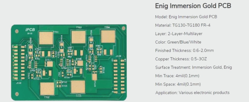
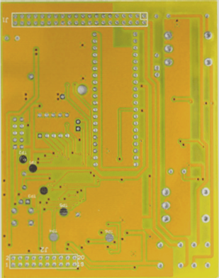
Fun Fact: PCB Colors
Did you know that not all PCBs are green? While some may only discover the term “PCB” in university, PCBs can come in various colors like black, purple, and more. The iconic green color of PCBs actually comes from a “green oil layer,” also known as a “solder mask,” which serves to protect the circuit and prevent short circuits.