WellCircuits specializes in producing high-precision and complex flex PCBs that include multilayer flex PCBs and ultra long flex PCBs along with 90° degree bending flexible circuits. The company specializes in manufacturing flex PCBs that range from 1 to 32 layers within China.
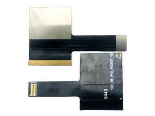
Flex PCB
What is a Flex PCB?
Are you struggling to fit complex electronics into a tiny enclosure? Does traditional wiring take up too much space and add unnecessary weight to your device? We know that modern product design demands more than just standard flat boards. A flex PCB (Flexible Printed Circuit Board) is the solution to these geometry challenges.
Unlike traditional rigid boards, a flexible printed circuit board is built on flexible base materials—typically polyimide—allowing the circuit to bend, fold, and twist without breaking electrical connections. These aren’t just fancy cables; they are fully functional circuits capable of supporting components while adapting to the unique shape of your product.
Key Advantages of Flexible PCB Boards
Switching to flexible circuits offers immediate benefits for high-performance applications where space is at a premium:
- Space Savings: You can eliminate bulky wire harnesses and connectors, reducing the overall package size by up to 75%.
- Weight Reduction: The thin dielectric materials make a flexible pcb board significantly lighter than rigid alternatives, which is critical for drones and wearables.
- Dynamic Flexibility: Our boards are designed to withstand millions of flex cycles, making them perfect for dynamic flex PCB applications like printer heads or folding smartphones.
- Reliability: Fewer interconnects mean fewer points of failure compared to traditional wiring assemblies.
Flex vs. Rigid vs. Rigid-Flex PCB
Understanding the difference between standard, flexible, and rigid-flex PCB technologies is crucial for determining the right stackup for your project.
| Feature | Rigid PCB | Flex PCB | Rigid-Flex PCB |
|---|---|---|---|
| Base Material | FR4 (Fiberglass) | Polyimide (PI) / Polyester | Hybrid (FR4 + PI) |
| Flexibility | None (Static) | High (Static or Dynamic) | Mixed (Foldable sections) |
| Space Efficiency | Low | High | Maximum (3D Packaging) |
| Primary Use | Motherboards, Power Supplies | Wearables, Flex PCB Connectors | Aerospace, Medical Devices |
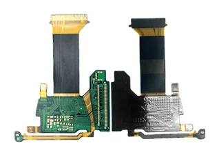
Types of Flexible Circuits We Offer
At WellCircuits, we understand that every project has unique mechanical and electrical demands. As a specialized flex circuit manufacturer, we provide a versatile range of board configurations designed to fit everything from simple connectors to high-density aerospace systems.
Single-Sided Flex Circuits
This is our most cost-effective solution for straightforward applications. Single-sided flex circuits consist of a single copper conductor layer bonded to a flexible dielectric film.
- Best For: Dynamic flexing applications and simple interconnects.
- Key Advantage: extremely thin profile and high flexibility.
Double-Sided Flex Circuits
When you need more routing power, double-sided flex circuits are the answer. These boards feature conductive layers on both sides of the base film, connected via plated through-holes (PTH).
- Best For: Designs requiring crossovers and higher circuit density.
- Key Advantage: Maintains flexibility while allowing for more complex component placement.
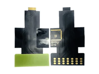
Multilayer Flex Circuits
For advanced electronics, we manufacture multilayer flex circuits supporting up to 32 layers. These complex boards utilize blind and buried vias to manage high-density interconnects without wasting space.
- Best For: High-performance devices with strict space constraints.
- Key Advantage: Solves complex shielding and impedance issues in a compact form factor.
Rigid-Flex PCB Hybrids
Our rigid-flex PCB technology combines the stability of a rigid board with the versatility of a flexible circuit. By integrating these technologies into a single unit, we eliminate the need for heavy connectors and cables.
- Best For: 3D packaging and vibration-resistant applications.
- Key Advantage: Improves reliability and signal integrity while simplifying assembly.
Our Manufacturing Capabilities
At WellCircuits, we push the limits of what a flex PCB manufacturer can do. While many suppliers stick to basic designs, we have the engineering depth to produce complex multilayer flex PCBs ranging from single-layer up to an impressive 32 layers. Our facility is equipped to handle high-precision requirements, ensuring your designs aren’t limited by manufacturing constraints.
Speed is critical for R&D. We stand out as a flex PCB prototyping partner capable of delivering results in as little as 7 days. This rapid turnaround allows you to test and validate designs quickly without the long wait times typically associated with offshore production.
Our technical capabilities cover the most demanding specifications in the industry:
- High-Density Interconnects (HDI): We utilize micro-vias and ultra-fine pitch technologies to pack more functionality into smaller footprints.
- Signal Integrity: We offer precise impedance control and high-frequency mixing options for reliable data transmission.
- Specialized Features: From thick copper for power applications to steel sheet reinforcements and ultra-long flex boards, we customize every board to meet your exact mechanical and electrical needs.
Flex PCB Material Selection & Specifications
Choosing the right flexible PCB material is the most critical step in the engineering process. The substrate defines how well your board handles thermal stress, chemical exposure, and mechanical bending. At WellCircuits, we strictly use high-grade materials to ensure our boards meet the rigorous demands of aerospace, medical, and consumer electronics markets.
Polyimide (PI) vs. Cost-Effective Alternatives
For the vast majority of our high-reliability projects, we use Polyimide (PI) substrates (often referred to by the brand name Kapton). A Polyimide flex PCB offers exceptional thermal stability and high tensile strength, making it the industry standard for complex multilayer and rigid-flex designs.
- Polyimide (PI): Best for high operating temperatures, soldering resistance, and dynamic flexing.
- Polyester (PET) & PEN: These are lower-cost options suitable for simple, single-sided applications where high heat and solderability are not primary concerns (often used in membrane switches).
- Fluoropolymers (FEP): Used in specialized high-frequency applications requiring low dielectric constants.
Copper Foil and Coverlay Options
The conductive layer performance depends heavily on the type of copper foil selected. We optimize flex PCB thickness and flexibility using two main copper types:
- Rolled Annealed (RA) Copper: The superior choice for dynamic flex applications (boards that bend repeatedly). Its grain structure allows for extensive flexing without cracking.
- Electro-Deposited (ED) Copper: Ideal for static applications where the board is installed once and doesn’t move.
Instead of the standard solder mask used on rigid boards, we typically use a Coverlay (Polyimide + Adhesive). This provides better flexibility and dielectric strength. For high-density designs with fine pitch components, we can also apply flexible liquid photoimageable (LPI) solder masks.
Flex PCB Stiffener Integration
Flexible circuits often need rigid support in specific areas to support heavy components or ensure proper connection into ZIF connectors. We integrate various Flex PCB stiffener materials depending on the function:
| Stiffener Material | Primary Function | Typical Application |
|---|---|---|
| FR4 | Provides rigid support for components | Underneath heavy ICs or connectors to prevent solder joint cracks. |
| Polyimide (PI) | Adjusts thickness for mating | Applied at contact fingers to fit ZIF connectors perfectly. |
| Stainless Steel / Aluminum | Heat dissipation & high strength | Used in our specialized designs requiring robust reinforcement or thermal management. |
We tailor the flex PCB stackup to balance flexibility with mechanical integrity, ensuring you get a board that survives the real world. whether you need a simple single-layer interconnect or a complex 32-layer build, we have the material stock to turn your design around quickly.
Flex PCB Design Guidelines
Designing a flexible printed circuit board requires a different mindset than standard rigid boards. Because these circuits must endure mechanical stress, specific rules apply to ensure the copper doesn’t crack under pressure. At WellCircuits, we provide comprehensive flex PCB design support to help you navigate these complexities, ensuring your board performs reliably whether it’s sitting still or constantly moving.
Critical Bend Radius: Static vs. Dynamic
The most common failure point in a flex pcb is the bend area. The “bend radius” refers to the minimum curvature a board can handle before the copper conductors or substrate begin to fracture. We categorize designs into two main types based on their movement requirements:
- Static Applications (Flex-to-Install): The circuit is bent once during assembly to fit into the housing and then remains fixed. These can generally tolerate a tighter bend radius (typically roughly 10x the material thickness).
- Dynamic Applications: The circuit flexes continuously during operation, such as in a printer head or a flip phone. For a dynamic flex pcb, the bend radius must be much larger (usually 20x to 100x the thickness) to prevent metal fatigue over time.
Trace Routing and Stack-up Strategy
To maintain signal integrity and mechanical durability, your flex pcb stackup and routing must be optimized for flexibility. Sharp angles act as stress concentrators that lead to tearing.
- Curved Traces: Avoid 90-degree corners. Use radiused (curved) corners for traces to distribute stress evenly.
- Staggered Conductors: In multilayer flex circuits, avoid stacking conductors directly on top of each other in bend areas. Staggering them prevents the “I-beam” effect, which increases stiffness and risk of breakage.
- Neutral Axis Placement: For dynamic designs, place the copper conductors in the center of the stack-up (the neutral axis) so they experience the least amount of tension or compression during bending.
- Via Placement: Never place vias or plated through-holes (PTH) in the bending zone. Vias are rigid structures and will crack if flexed.
DFM Tips to Avoid Trace Cracking and EMI
Our engineering team performs rigorous DFM checks to catch potential issues before manufacturing begins. Here are key practices to improve yield and performance:
- Cross-Hatched Ground Planes: Solid copper planes are stiff and prone to cracking. We recommend using a cross-hatched pattern for ground planes to maintain flexibility while still providing EMI shielding.
- Teardrops and Anchors: Add teardrops to pad-to-trace junctions and use anchoring spurs (tie-downs) for pads. This prevents the copper from peeling off the polyimide substrate during soldering or mechanical stress.
- Thermal Management: Flexible materials like polyimide dissipate heat differently than FR4. Proper spacing and the use of thermal vias are critical to managing thermal stress, especially in high-current applications.
Technical Standards & Certifications
When you order a flex PCB from us, you aren’t just getting a circuit; you are getting a guarantee of reliability. We understand that for US markets—especially in medical and aerospace sectors—compliance isn’t optional. We manufacture strictly according to international standards to ensure every board performs under stress, vibration, and thermal cycling.
Manufacturing Compliance & Quality Assurance
Our facility operates under a robust quality management system. We ensure that every flexible printed circuit board leaving our line meets the rigorous demands of modern electronics.
- IPC-6013: We build to Class 2 and Class 3 specifications for flexible printed boards, ensuring high reliability for critical applications.
- ISO 9001: Our processes are certified for consistent quality management and continuous improvement.
- UL 94V-0: We use materials that meet strict flammability safety standards, essential for consumer and industrial safety.
Standard Capabilities & Tolerances
Precision is key when dealing with flexible materials like Polyimide. Below is a snapshot of our standard manufacturing specifications and surface finishes.
| Feature | Specification / Standard |
|---|---|
| Layer Count | 1 to 32 Layers |
| Base Material | Polyimide (PI), PET, PEN |
| Min. Trace Width/Spacing | 3mil / 3mil (0.075mm) |
| Drill Tolerance | ±0.05mm (PTH), ±0.025mm (NPTH) |
| Surface Finishes | ENIG, Immersion Silver/Tin, OSP, Hard Gold |
| Impedance Control | ±10% Tolerance |
By sticking to these strict flex PCB design guidelines and manufacturing tolerances, we deliver boards that fit perfectly into your assembly process without the headache of fitment issues or electrical failures.
Industry Applications & Use Cases for Flex PCBs
The versatility of flexible printed circuit boards has made them indispensable across high-tech sectors. At WellCircuits, we engineer boards that solve specific physical and electrical challenges, from tight static bends in handheld gadgets to continuous dynamic flexing in robotic arms. Here is how our flex PCB technology powers innovation across major industries.
Consumer Electronics
In the fast-paced world of consumer tech, miniaturization is everything. Our flex circuits allow designers to pack more functionality into smaller, lighter housings.
- Wearables: Smartwatches and fitness trackers rely on our ultra-thin boards to conform to curved casing shapes.
- Smartphones & Cameras: We provide high-density interconnects that handle complex signals within the limited space of modern mobile devices and digital cameras.
- Foldable Devices: Our dynamic flex PCB solutions are engineered to withstand thousands of folding cycles without signal degradation.
Medical Devices
Reliability is critical when human health is on the line. Our manufacturing process meets stringent standards required for medical-grade electronics.
- Implantables: We utilize biocompatible materials like Polyimide to create circuits for pacemakers and cochlear implants that are lightweight and durable.
- Diagnostic Equipment: Our multilayer flex circuits support the complex data processing needs of portable imaging systems and patient monitoring devices.
- Hearing Aids: The extreme flexibility of our boards allows for comfortable, discreet designs that fit within the ear canal.
Automotive and Industrial Systems
Modern vehicles and factory equipment demand electronics that can survive harsh environments. Our boards are built to resist vibration, heat, and chemical exposure.
- Automotive Control Modules: From dashboard displays to engine sensors, our rigid-flex PCB solutions reduce weight while maintaining robust connections under constant road vibration.
- Robotics: For industrial arms and automation, we design dynamic flex PCBs capable of enduring millions of flex cycles without copper fatigue.
- Sensors: We produce flexible substrates that allow sensors to be mounted on irregular surfaces in engine bays and manufacturing lines.
Aerospace and Defense
In aerospace, every gram counts. Our flex PCBs offer significant weight reduction compared to traditional wiring harnesses, which translates to fuel efficiency and higher payload capacity.
- Vibration Resistance: The low mass and ductility of our circuits make them immune to the high-vibration environments of launch vehicles and aircraft.
- Satellite Systems: We manufacture high-reliability boards that function correctly in the extreme thermal cycling of space.
- Defense Electronics: Our robust rigid-flex designs provide secure, shock-resistant interconnects for mission-critical communication and navigation hardware.
Why Choose WellCircuits as Your Flex PCB Manufacturer?
As a premier flex PCB manufacturer, WellCircuits delivers the engineering precision required for high-stakes industries like aerospace, medical, and consumer electronics. We distinguish ourselves as an elite maker capable of producing complex multilayer flex circuits up to 32 layers, going far beyond the standard capabilities of typical board houses. Our facility is optimized to handle everything from ultra-thin profiles to heavy-duty rigid-flex PCB builds, ensuring your specific design requirements are met with exact tolerances.
We understand that time-to-market is critical for our US clients. That is why we position ourselves as the “China First 7-Day Delivery PCB Factory,” streamlining the process from flex PCB prototyping to final assembly.
Our Competitive Advantages:
| Feature | Benefit to You |
|---|---|
| Rapid Speed | Fast-turnaround options with 7-day delivery to keep your project on schedule. |
| Expert Support | Comprehensive, free DFM checks to verify your flex PCB design guidelines and prevent manufacturing issues. |
| Risk-Free Testing | We offer free samples so you can validate our quality and materials before full-scale production. |
| Advanced Tech | Specialized capabilities including impedance control, ultra-long flex boards, and 90° bending circuits. |
By partnering with us, you gain access to factory-direct pricing without sacrificing the reliability or technical support needed for advanced flexible printed circuit board applications. We handle the complexities of manufacturing so you can focus on innovation.
Flex PCB Frequently Asked Questions
What is the typical lead time for a Flex PCB order?
Speed is our priority. As a specialized flex circuit manufacturer, we offer some of the fastest turnaround times in the industry. For standard prototypes, we can achieve a 7-day delivery timeline. Complex multilayer flex circuits (up to 32 layers) or rigid-flex PCB designs may require slightly longer production windows depending on the stackup complexity and material availability.
Do you have a Minimum Order Quantity (MOQ)?
We understand that every project starts with a prototype. We do not enforce strict high-volume MOQs. We offer free samples for many standard specifications to help you validate your design before committing to mass production. Whether you need a single flex PCB prototype or a full production run, we scale with your needs.
How does the cost compare between Rigid and Flex PCBs?
Generally, a flexible printed circuit board costs more upfront than a standard rigid board due to specialized materials like polyimide and more complex manufacturing steps. However, flex PCBs often reduce the total cost of the final assembly by eliminating connectors, wire harnesses, and reducing enclosure sizes.
Rigid vs. Flex PCB: Which one do I need?
Choosing between a standard rigid board and a flexible circuit board depends on your mechanical requirements. If your device requires the board to bend during use (dynamic) or fit into a tight, non-linear space (static), flex is the answer.
Comparison: Rigid vs. Flexible PCB
| Feature | Rigid PCB | Flex PCB |
|---|---|---|
| Flexibility | None (Structural support only) | High (Dynamic bending & folding) |
| Weight & Space | Heavier, requires more vertical space | Ultra-thin, lightweight, space-saving |
| Vibration Resistance | Low (Solder joints may crack) | High (Absorbs shock & vibration) |
| Interconnects | Requires cables/connectors | Integrated traces (No cables needed) |
| Primary Use | Motherboards, Desktop Electronics | Wearables, Medical, Aerospace |
Can you manufacture High-Density Interconnect (HDI) Flex PCBs?
Yes. Our facility in China is equipped to handle advanced high-density flex PCB designs. We support micro-vias, blind/buried vias, and ultra-fine pitch traces necessary for modern smartphones and medical devices. We also provide impedance control to ensure signal integrity in high-frequency applications.
Introduction to Flexible Circuits
Flexible circuits, often referred to as flex circuits, represent a transformative advancement in printed circuit board (PCB) technology. Unlike traditional rigid boards, flexible circuits are constructed on a flexible substrate, allowing them to bend, fold, and twist to fit into compact or irregularly shaped spaces without compromising performance. This flexibility is achieved through a multi-layered structure, typically consisting of a conductive layer—most commonly copper—sandwiched between a flexible dielectric layer such as polyimide or polyester, and a protective layer that shields the circuit from moisture, dust, and extreme temperatures.
The unique construction of flexible circuits enables the integration of complex electronic pathways within a lightweight and durable format. The protective layer not only guards against environmental hazards but also enhances the longevity and reliability of the circuit, making it ideal for use in demanding applications. Flexible circuits are widely used in medical devices, where their ability to conform to small, intricate spaces is crucial, as well as in consumer electronics, where space constraints and lightweight designs are paramount. By leveraging the inherent advantages of flexible substrates and advanced layering techniques, flex circuits have become a cornerstone of modern electronic design, supporting innovation across a diverse range of industries.
Applications
The versatility of flexible circuits has led to their widespread adoption across numerous industries, where their unique properties deliver significant benefits. In consumer electronics, flexible circuits are found in smartphones, tablets, laptops, and wearable devices, enabling sleek, compact designs and reliable connections between densely packed components. Their ability to bend and flex without breaking makes them essential for devices that require frequent movement or folding.
In the medical field, flexible circuits are integral to the development of advanced medical devices such as pacemakers, implantable cardioverter-defibrillators, and portable monitoring equipment. Their lightweight and adaptable nature allows for minimally invasive designs and enhances patient comfort, while maintaining the high reliability required for life-critical applications.
Aerospace and defense sectors also rely heavily on flexible circuits for satellites, spacecraft, and aircraft systems, where weight reduction, durability, and the ability to withstand vibration and thermal cycling are critical. Additionally, flexible circuits are used in industrial automation, robotics, and control systems, where they provide robust and efficient connections in environments that demand both flexibility and reliability.
By enabling reduced size and weight, improving reliability, and offering unparalleled design flexibility, flexible circuits continue to drive innovation in electronic products and systems across the globe.
Design Considerations
Designing flexible printed circuit boards (flex PCBs) requires a strategic approach that balances electrical performance, mechanical durability, and manufacturability. Unlike traditional rigid boards, flexible circuits must endure repeated bending, twisting, and folding, all while maintaining reliable electrical connections and meeting the stringent requirements of modern electronic devices.
A critical first step in flex PCB design is the careful selection of the base material. Polyimide films are widely favored for their advantageous electrical, mechanical, and thermal properties, making them the backbone of most flexible printed circuit boards. These materials provide the flexibility needed for dynamic applications while ensuring the circuit can withstand high temperatures and harsh environments, which is especially important in medical devices and aerospace systems.
The design of the conductive layer is equally important. Copper foil is the standard choice due to its excellent conductivity and flexibility. The thickness of the copper layer must be optimized: too thick, and the circuit loses flexibility; too thin, and it may not handle the required current or mechanical stress. For multilayer flex circuits, careful planning of conductor routing and via placement is essential to maintain signal integrity and reliable electrical connections across all layers.
Protective layers, such as polyimide coverlays or flexible solder masks, are applied to shield the conductive traces from moisture, dust, and mechanical abrasion. These layers not only enhance reliability but also help prevent electromagnetic interference (EMI), which can be more pronounced in flexible circuits due to their thin profiles and close proximity to other electronic components.
Space constraints are a defining factor in flex PCB design, particularly in consumer electronics and medical devices where every millimeter counts. Designers must optimize circuit layouts to maximize functionality within minimal space, often employing advanced flex PCB design techniques to route traces efficiently and avoid unnecessary complexity. The assembly process for flexible PCBs can also be more intricate than for rigid boards, requiring specialized equipment and handling procedures to prevent damage during component placement and soldering.
Thermal management is another key consideration. Flexible PCBs, by nature of their thin and lightweight construction, can be more susceptible to heat buildup. Incorporating thermal vias, heat spreaders, or selecting base materials with superior thermal properties can help dissipate heat and maintain optimal performance, even in demanding applications.
Electromagnetic interference is a potential challenge in flex circuit construction, as the flexible sections can act as antennas if not properly shielded. Employing ground planes, shielding layers, or strategic trace placement can mitigate EMI and ensure signal integrity, which is vital for high-speed or sensitive electronic devices.
Component selection must also align with the flexible nature of the circuit. Surface-mount technology (SMT) components are typically preferred, as they are lightweight and can better withstand the mechanical stresses of flexing. The assembly process should be tailored to accommodate the unique handling requirements of flexible PCBs, ensuring that components remain securely attached throughout the product’s lifecycle.
Different types of flex PCBs—whether single layer, double sided flex, or multilayer flex circuits—each present unique design challenges. For example, double sided flex PCBs require precise via design to ensure robust electrical connections between layers, while multilayer designs demand careful management of layer stacking and interconnections to avoid signal loss or crosstalk.
Ultimately, successful flex PCB design hinges on a holistic understanding of materials, electrical requirements, mechanical stresses, and assembly processes. By addressing these considerations from the outset, engineers can create flexible printed circuits that deliver high reliability, superior performance, and the space-saving advantages demanded by today’s advanced electronic products. For applications requiring even greater versatility and durability, rigid flex PCBs offer a compelling solution by combining the strengths of both rigid and flexible technologies in a single, integrated design.
Reliability
Reliability is a defining characteristic of flexible circuits, making them the preferred choice for applications where consistent performance is non-negotiable. Engineered to endure a wide range of environmental stresses—including extreme temperatures, vibration, and moisture—flexible circuits are manufactured using high-quality materials and advanced fabrication techniques that ensure long-term durability.
The robust design of flexible circuits allows them to maintain electrical integrity even in harsh environments, such as those encountered in aerospace, automotive, and industrial settings. Their construction minimizes the risk of mechanical failure, as the flexible substrate absorbs shocks and vibrations that could otherwise damage traditional rigid boards. Furthermore, the manufacturing process for flexible circuits incorporates rigorous testing and inspection protocols, enabling early detection and correction of defects to enhance overall product reliability.
By providing a dependable means of connecting electronic components in challenging conditions, flexible circuits help OEMs and engineers achieve high reliability in their end products. This reliability, combined with their adaptability and performance, continues to expand the use of flexible circuits in mission-critical applications where failure is not an option.
Flexible Circuit Base Material
The base material forms the backbone of flexible printed circuit boards, playing a pivotal role in determining their flexibility, durability, and electrical performance. In flexible circuits, the choice of base material directly influences how well the board can withstand repeated bending, thermal cycling, and the rigors of assembly, making it a key consideration for engineers designing advanced electronic devices.
Polyimide films, such as Kapton, are the most prevalent owing to their exceptional high temperature resistance, chemical stability, and ability to retain advantageous electrical properties across a broad temperature range. These flexible polyimide substrates are lightweight and can be manufactured in extremely thin layers, which is essential for applications where space savings and lightweight designs are critical—such as in medical devices, consumer electronics, and aerospace systems. The polyimide base material is typically laminated with a conductive layer, most commonly copper foil, to form the circuit paths that carry electrical signals throughout the flexible printed circuit board.
Polyethylene naphthalate (PEN) is another popular base material, valued for its good mechanical stability and cost-effectiveness. While not as heat-resistant as polyimide, PEN offers sufficient thermal properties for many standard applications and is often chosen when budget constraints are a priority.
Other materials, such as polyester (PET) and fluoropolymers (FEP), are also used in specific scenarios. PET provides a balance of flexibility and electrical performance at a lower cost, making it suitable for high-volume, cost-sensitive products. FEP, on the other hand, is selected for its outstanding chemical resistance and ability to perform in harsh environments where exposure to aggressive chemicals or extreme temperatures is expected.
The selection of base material impacts not only the mechanical and thermal properties of the flexible printed circuit board but also factors such as assembly process, lead time, and overall cost. For example, high-performance polyimide films may increase material costs but enhance reliability and lifespan in demanding applications, while PET may be preferred for simpler, disposable electronic products.
Ultimately, the base material is a critical factor in flex PCB design, influencing everything from the board’s thickness and flexibility to its ability to handle heat dissipation and maintain signal integrity. By carefully matching the base material to the specific requirements of the application, engineers can ensure that their flexible printed circuits deliver optimal performance, reliability, and value.