PCB Layout: Understanding the Physical Structure and Design Techniques
Types of Assembly
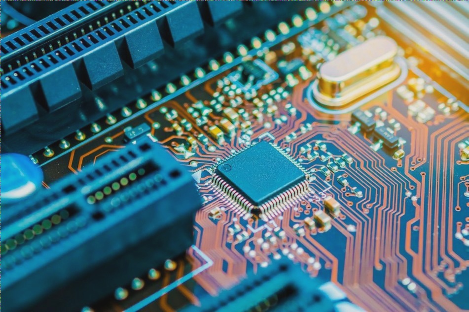
- PCB layout is influenced by the physical structure of the circuit board, which can utilize through-hole assembly, surface mount technology (SMT), or a combination of both.
- Through-hole assembly involves mounting components with wire leads into drilled holes, suitable for larger components needing a strong connection.
- Surface mount technology mounts components directly onto the PCB surface, allowing for smaller components and higher density.
- Combining through-hole and SMT components offers versatility in component options and configurations.
Board Layout Considerations
The physical structure of the circuit board impacts trace routing, component placement, and overall design. PCB experts must carefully consider this when designing:

Board Layout Tips:
- Use different grid settings for various stages of circuit board design.
- Choose grid accuracy based on component size for optimal alignment and aesthetics.
Board Layout Rules:
- Components should generally be on the same side of the board.
- Arrange components parallel or perpendicular to each other for a neat layout.
- Maintain a minimum spacing between solder pad patterns of different components.
Board Layout Techniques:
- Design layout based on the functions of circuit units.
- Arrange components around core functional unit components.
- Consider distribution parameters for high-frequency circuits.
Special Components and Layout Design:
Key components in high-frequency parts, core circuit components, and others require careful analysis to ensure proper placement for circuit functionality and production needs.
PCB Special Components Placement Guide
When designing the placement of special components on a PCB, the size of the board is a critical factor to consider. An oversized PCB can lead to longer printing lines, increased impedance, decreased anti-drying ability, and higher costs. Conversely, a PCB that is too small may suffer from poor heat dissipation and potential signal interference between adjacent lines.
Key Principles for Special Components Placement:
- Minimize the distance between high-frequency components to reduce electromagnetic interference.
- Avoid placing components susceptible to interference too close to each other.
- Increase the distance between components with high potential differences to prevent short circuits.
- Secure heavy components with brackets to prevent damage and consider heat dissipation.
- Balance the layout of adjustable components for accessibility and structural integrity.
Importance of PCB Board Layout
The layout of a PCB is crucial for the success of electronic products. Professional layout technicians often use advanced CAD software to optimize efficiency and identify potential design issues. A well-executed layout can save space, reduce the need for jumpers, and lower costs, making it a critical step in the PCB design process.