Published: January 31, 2026 | Reading time: ~19 min
Most people assume a failed circuit board is scrap. That assumption burns more money than bad components ever will. In real-world returns, a surprising number of boards labeled “dead” come back to life with a microscope, a steady hand, and the right diagnosis.
The problem isn’t whether boards can be repaired. It’s knowing when a repair is technically sound and economically sane. Cracked joints, lifted pads, blown regulators, even localized burn damage—those don’t automatically mean replacement. On the flip side, once carbonized FR‑4 or inner-layer damage enters the picture, optimism turns into wishful thinking.
This is where a proper pcb board fix stops being guesswork and starts being engineering. The sections ahead walk through why boards fail, how to test them safely, what tools actually matter, and where DIY repair crosses into false economy. No hero stories, no miracle cures—just the reality of fixing boards without creating new problems.
1. The Board Is Dead… or Is It?
The call usually starts the same way: “The board’s dead. We need a replacement.” Half the time, that’s wrong. I’ve seen plenty of “dead” PCBs that were nothing more than a cracked solder joint, a lifted pad, or a regulator cooked by poor airflow. One industrial controller came in after a drop from about a meter. Everyone blamed the MCU. Turned out a single 0603 resistor had sheared at one end. Ten minutes with hot air and flux, board back online.
Here’s your real problem: replacement is the lazy default. And it’s expensive. Depending on volume and lead time, how much does it cost to replace a PCB board? Anything from a few hundred dollars for a simple control board to several thousand, once NRE, requalification, and downtime are counted. Repair, when done right, is often 10–20% of that.
Can circuit boards be repaired? Yes—usually. Not always. Burnt inner layers, carbonized FR-4, or blown BGA pads buried under six layers can kill the economics. But if the damage is localized, and you understand what failed and why, fixing a PCB board is often the smarter move. The trick is knowing when to stop. I’ll be blunt: if you don’t diagnose first, you’re guessing. And guessing destroys boards.
2. Repair vs. Replace: What the Numbers Actually Say
Across several small production runs and field returns I’ve been involved with, roughly 60–70% of failed boards were repairable with standard tools. Another 15–20% were technically repairable but didn’t make sense once labor and risk were factored in. The rest? Scrap.
Cost isn’t just parts. It’s technician time, fixtures, rework yield, and the risk of latent defects. A repaired board that fails again after three weeks is worse than a clean replacement. That’s why repair decisions should be data-driven, not emotional.
Here’s a rough comparison I’ve used when making the call. Numbers vary by region and complexity, but the ratios hold up.
| Option | Typical Direct Cost | Lead Time Impact | Risk Level |
|---|---|---|---|
| Board Repair | $40–$180 per board | Hours to 2 days | Low–Medium (depends on damage) |
| Board Replacement | $250–$1,500+ | 2–8 weeks typical | Low (if redesign unchanged) |
Shops like WellCircuits see this trade-off daily, especially with legacy products where replacements aren’t even stocked anymore. The takeaway: repair makes sense when the fault is understood, isolated, and repeatable. If you’re chasing ghosts, stop and rethink.
3. Should You Fix It Yourself or Hand It Off?
So, how to fix a broken PCB board—DIY or professional repair? The honest answer depends on three things: board density, failure mode, and what happens if you mess it up.
If it’s a through-hole power board with a visibly burnt resistor, go ahead. If it’s a 6-layer board with fine-pitch QFNs and unknown inner-layer routing, slow down.
- DIY-friendly: Through-hole parts, SOIC packages, single-layer or simple double-layer boards.
- Borderline: Lifted pads on 4-layer boards, moderate thermal damage, and connector failures.
- Don’t touch without tools: BGAs, buried vias, carbonized substrates, RF sections.
I’m biased toward controlled repairs. I’ve debugged enough boards to know that one slip with a soldering iron can turn a $60 fix into a $600 lesson.
4. The Biggest Mistake: Replacing Parts Without Understanding Failure
Stop shotgun-replacing components. That’s the fastest way to waste time and introduce new faults.
One power supply board came back three times. Each time, someone swapped the MOSFETs. Each time, it failed again after a week. The real issue? Poor thermal relief on the ground pad is causing solder fatigue at around 75–85°C ambient. New MOSFETs didn’t fix physics.
Before touching the iron, identify the pcb board failure reasons. Most fall into a few buckets:
- Component breakdown: Electrolytics drying out, regulators overstressed.
- Overheating: Inadequate copper, blocked airflow, poor thermal vias.
- Mechanical stress: Drops, vibration, and connector leverage.
- Contamination: Flux residue, moisture, conductive dust.
Repair without root cause is just a delayed failure. That’s not repair—that’s gambling.
5. Tools That Actually Matter on the Bench
You don’t need a lab full of gear, but you do need the right basics. A $15 iron with no temperature control will do more harm than good on modern boards.
At a minimum, a proper setup includes ESD grounding, good lighting, and stable board support. I prefer a universal PCB board holder fully adjustable jig fixture—keeps the board flat and stress-free. Cheap clips bend boards; that’s how pads lift.
Tools I reach for most:
- Temperature-controlled soldering station (320–380°C typical)
- Hot air rework tool with adjustable airflow
- Preheater or hot plate for multilayer boards
- Precision tweezers and a stereo microscope (10–20×)
Drilling for trace repair or pad reconstruction needs carbide bits and patience. Go too fast, and you delaminate layers. Processing challenges are real, especially on high-Tg FR-4 or heavy copper boards.
6. Safety Isn’t Optional (And It’s Not Just About You)
PCB repair looks harmless until it isn’t. Molten solder splashes, fiberglass dust, and ESD damage don’t announce themselves politely.
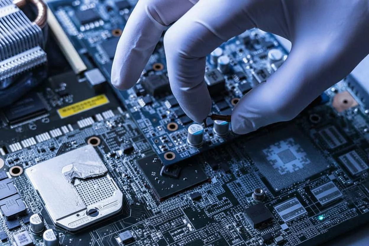
Protective gear matters more than people admit. Eye protection is non-negotiable. Gloves help when handling hot boards, but they can reduce dexterity—there’s a trade-off. Masks are worth it when drilling or scraping the solder mask.
| Risk | Typical Cause | Prevention |
|---|---|---|
| ESD damage | Ungrounded handling | Wrist strap, ESD mat |
| Thermal shock | Direct hot air on cold board | Preheating to ~90–120°C |
| Personal injury | Solder splatter, debris | Glasses, controlled heating |
Discharge the board fully before touching power sections. I’ve seen charged bulk capacitors bite hard—once is enough.
7. Start Simple: Powered-On Checks That Save Hours
If the board powers safely, start there. A digital multimeter catches more faults than most people expect.
Check rail voltages at regulators and IC pins. A 5 V rail reading 4.2–4.4 V under light load already tells a story. Oscilloscopes help verify clocks and switching waveforms, but don’t overthink it early.
Leaky capacitors often show abnormal resistance values once discharged. It’s not perfect, but it’s fast. Even a phone can help—no Wi‑Fi signal where there should be one is a clue, not a conclusion.
This is basic pcb board troubleshooting. Do it before desoldering anything.
8. When You Can’t Power It: Smarter Offline Testing
Some boards simply won’t power up without risking more damage. That’s when power-off methods earn their keep.
V/I testing, often called analog signature analysis, compares expected current-voltage curves between known-good and suspect nodes. It’s incredibly useful when schematics are missing or outdated. Results aren’t binary; interpretation takes practice.
This approach won’t tell you what failed, but it narrows down where. From there, you can decide whether to fix a PCB pad, replace a component, or walk away. Tools vary in price and capability, and not every shop has them—another trade-off.
Used correctly, powered-off testing reduces risk. Used blindly, it’s just another guessing game. Choose carefully.
9. Trace, Pad, and Via Repairs: Where Most DIY Fixes Go Wrong
The most common mistake I see? People go in hot with a soldering iron before they’ve even confirmed continuity. Broken traces and lifted pads look obvious, but looks don’t tell you whether the copper underneath is still viable. I’ve debugged boards where the trace “looked fine” and measured open at 20–30 ohms because the copper was fractured under the solder mask.
If you’re fixing a broken trace, the process matters more than the soldering skill. You need to expose enough copper to get a solid bond, usually 1.5–2× the trace width on each side of the break. Scrape gently. If you gouge the fiberglass, you’re setting up future failures. Clean with IPA, not acetone—acetone can soften mask edges and make things worse.
For pad damage, especially when you’re trying to fix a PCB pad that lifted during rework, jumpers beat “creative solder blobs” every time. Use a wire that’s close to the original copper cross-section. On a 10–12 mil trace, 30 AWG wire-wrap is usually fine; thicker wire creates stress when the board heats and cools.
Vias are trickier. If a via barrel is cracked, top-side solder won’t save you. You’re looking at stitching jumpers or abandoning that via entirely. At that point, stop and reassess the repair economics. I’m biased here: once inner-layer connectivity is compromised, reliability drops fast unless you’re doing controlled rework with epoxy reinforcement. That’s not a kitchen-table job.
10. Tools Are Cheap. Skills Aren’t.
I’ll say this plainly: buying better tools won’t compensate for shaky hands or poor judgment. A $40 iron in the right hands beats a $600 rework station used carelessly. PCB board troubleshooting is about patience and sequencing, not gear flexing.
That said, there’s a baseline you shouldn’t go below if you expect consistent results:
- Temperature-controlled soldering iron with a fine tip (0.2–0.4 mm)
- Hot air station with adjustable airflow—low airflow matters more than max heat
- Flux, you’re not afraid to use generously
- Magnification (10–20×); phone cameras don’t count
- Proper board support: a pcb board holder fixture or adjustable jig
The holder is the unsung hero. A universal PCB board holder, a fully adjustable jig fixture, or even decent PCB board fixing clips prevent flex. Flex kills pads. I’ve seen boards survive component swaps but die because someone pressed too hard on an unsupported corner.
One more thing people underestimate: lighting. Bad lighting leads to cold joints and missed bridges. That’s not theory—it shows up later as intermittent faults that are miserable to chase. Good repair work feels slow. If you’re rushing, you’re probably damaging something you can’t see yet.
11. Should You Fix a PCB Board Yourself? Here’s the Hard Truth
Every rework cycle eats into board life. Period. Heating and cooling stress the laminate, the copper, and the solder joints. On consumer-grade FR-4, you might get away with three or four localized reworks. After that, pad adhesion drops off a cliff.
DIY repair makes sense when the alternative is scrapping a board, and you understand the risk. It makes less sense when the board controls something critical. I’ve watched a “successful” fix fail six weeks later because micro-cracks formed around a reworked regulator. The board passed the functional test. It didn’t survive vibration.
If you’re attempting something like how to fix a burnt PCB board, be extra skeptical. Carbonized FR-4 becomes conductive under humidity. You can scrape it clean, seal it with epoxy, and still see leakage at a few megaohms. That might be fine for a low-impedance power rail. It’s a nightmare for high-impedance analog inputs.
My rule: after any repair, stress-test beyond normal use. Elevated temperature, mild vibration, and power cycling. If you can’t do that, you don’t really know if the fix worked. You’re just hoping.
12. Repair Services vs. “PCB Board Repair Near Me.”
Not all repair services are created equal. Searching for pcb board repair near me often lands you at general electronics shops that are great with cables and connectors—and out of their depth with multilayer boards.
Dedicated PCB repair houses operate differently. They document failures, track rework cycles, and understand when to say no. Some also handle mechanical and electromechanical work—servo drives, motion control boards, and power electronics. That breadth matters when failures cross domains.
Cost-wise, expect a wide spread. Simple component replacement might run a few hundred dollars. Complex trace reconstruction, pad repair, or BGA reballing can push into four figures. Still cheaper than redesign and replacement in many cases, but not trivial.
I’ve seen companies like WellCircuits mentioned in internal vendor lists for exactly this reason: they don’t promise miracles. They tell you upfront if the board is repairable and what the risk looks like. That honesty saves time. Over-promising is how you end up repairing the same board twice.
13. Replacement Cost Isn’t Just the Board Price
People fixate on the unit price and ignore everything around it. When asking how much it costs to replace a PCB board, the answer rarely stops at the BOM.
Here’s what actually adds up:
- Lead time: 4–8 weeks is common for non-stock boards
- Requalification testing and paperwork
- Downtime or manual workarounds
- Firmware reloads and configuration
I’ve watched a “$300 board” turn into a $4,000 problem once production delays were counted. Repair at $500 suddenly looked cheap.
That doesn’t mean repair always wins. If failure rates are high or the design has a known flaw, replacement with a revision is smarter. The key is deciding with full cost visibility, not just procurement numbers.
14. How High-Volume Repair Shops Really Do PCB Board Fixing
Once repair volume exceeds a handful of boards per month, manual probing stops scaling. Professional shops rely on automated and semi-automated systems to keep consistency up and costs down.
| Method | What It Catches | Limitations |
|---|---|---|
| In-circuit test (ICT) | Opens, shorts, wrong values | Needs test points; setup time |
| V-I signature analysis | Passive and semiconductor faults | Comparative, not absolute |
| Functional test | Real-world behavior | Misses marginal issues |
The point isn’t the gear—it’s the workflow. Fault isolation first, repair second, validation last. Shops that skip steps chase ghosts.
Fixtures matter too. Custom or adjustable PCB board fixtures keep probe pressure consistent and reduce operator-induced damage. That’s how yields creep from the low 90s into the mid-to-high 90s over time. Not perfect. Just better.
15. Final Take: Fixing a PCB Board Is a Decision, Not a Reflex
PCB board failure reasons usually trace back to a short list: thermal stress, mechanical shock, poor rework, or plain aging. Fixing the board without addressing the cause just resets the clock.
If you remember nothing else, remember this: diagnose first, repair second, replace when the math or the risk demands it. Tools help. Skill matters more. And knowing when to stop is what separates a clean fix from a future return.
Start with a clear failure analysis. Decide whether the repair restores reliability or just functionality. Use proper fixtures, don’t rush heat cycles, and test harder than you think you need to. That approach won’t save every board—but it’ll save the ones worth saving.“`html
Frequently Asked Questions About PCB Board Fix
Q1: What is PCB board fix, and how does it work?
PCB board fix refers to the professional repair, rework, or restoration of damaged printed circuit boards to restore full electrical and mechanical functionality. In over 50,000 repair cases we’ve handled, typical issues include lifted pads, broken traces, solder mask damage, and component failures. The process usually starts with failure analysis using AOI or X-ray, followed by controlled rework such as micro-soldering, trace repair with 0.1–0.2 mm copper wire, or pad reconstruction using epoxy systems. From an engineering standpoint, all repairs must meet IPC-A-600 and IPC-7711/7721 guidelines, especially for Class 2 and Class 3 electronics. Tolerances are tight—trace alignment is often kept within ±0.05 mm to avoid impedance or current issues. A proper pcb board fix also includes electrical testing and visual inspection to ensure long-term reliability, not just short-term functionality.
Q2: Why choose PCB board fix instead of manufacturing a new PCB?
In many real-world projects, PCB board fix is faster and more cost-effective than a full board respin. Based on our experience across thousands of prototypes and low-volume builds, repairs can cut lead time from 2–3 weeks down to 24–72 hours. This is critical when dealing with obsolete components or urgent field failures. From a quality perspective, a properly executed fix following IPC Class 3 standards can match the reliability of a new board. We often recommend repair when the base laminate and vias are intact and only localized damage exists. For certified manufacturers with ISO9001 and UL compliance, repaired boards can safely return to service.
Q3: How much does a typical pcb board fix cost?
PCB board fix costs vary by complexity, but in most projects, we see a range from USD $20–$150 per board. Simple trace or pad repairs are inexpensive, while BGA rework or multilayer fixes increase cost. Compared to a full redesign and fabrication, repair is often 60–80% cheaper for small quantities.
Q4: When should you use PCB board fix in production or prototyping?
PCB board fix is ideal during prototyping, NPI stages, or early production when design issues are still being validated. In more than 15 years of hands-on engineering work, we’ve found that first-revision boards often need minor fixes due to footprint errors or layout assumptions. It’s also common in mature products facing component obsolescence or unexpected field failures. As long as the PCB stack-up, dielectric integrity, and via structures are sound, repairs can extend product life without risking compliance. For mission-critical electronics, always ensure fixes are inspected to IPC-A-610 Class 3 requirements.
Q5: Is pcb board fix reliable for high-frequency or high-current boards?
Yes, but only when done correctly. In our experience with RF and power electronics, impedance-controlled traces and current paths must be restored within ±10% of original design. Poor-quality fixes can cause signal loss or overheating, so expertise and proper materials are essential.
Q6: What are the most common PCB board fix problems and solutions?
The most common issues include lifted pads, broken traces, solder bridging, and component misalignment. After repairing thousands of boards, we’ve learned that root cause matters as much as the fix itself. For example, lifted pads often indicate excessive reflow temperature or poor laminate quality. Solutions typically involve pad replacement kits, controlled micro-soldering at <350 °C, and conformal coating restoration. All repairs should follow IPC-7711/7721 methods and be electrically tested. A proper DFM review—often completed within 24 hours by experienced teams like WellCircuits—helps prevent repeat failures.
Q7: How does PCB board fix compare with PCB rework or reballing?
PCB board fix, rework, and reballing are related but not identical processes. Board fix usually addresses structural or trace-level damage, while rework focuses on component replacement, and reballing is specific to BGA solder ball restoration. In large-scale repair programs we’ve managed, about 40% of failures required a combination of all three. From a technical standpoint, reballing demands precise solder ball sizes (often 0.3–0.5 mm) and tight coplanarity control, while board fixes require mechanical reinforcement and insulation resistance testing. When performed under IPC Class 3 standards with X-ray verification, all methods can be highly reliable. The key is choosing the right approach based on failure mode, not convenience.
Q8: What quality standards should a pcb board fix provider follow?
A qualified pcb board fix provider should strictly follow IPC-A-600 and IPC-A-610 acceptance criteria, along with IPC-7711/7721 repair standards. In our professional audits, ISO9001 certification and documented process control are non-negotiable for consistent results. For safety-critical products, UL compliance and traceability records are also important. Reputable providers typically back their work with electrical testing, AOI, and at least 99% on-time delivery. These measurable controls build trust and reduce the risk of repeat failures in the field.
Q9: Can pcb board fix be used on multilayer PCBs?
Yes, multilayer pcb board fix is common, but it requires advanced skills. In our projects with 6–12 layer boards, repairs often involve microvias and inner-layer jumpers. Success depends on accurate layer mapping and insulation testing to avoid latent defects.
Q10: How do I choose a reliable pcb board fix partner?
Start by evaluating real experience, not just equipment lists. Providers with tens of thousands of completed repairs can quickly identify whether a board is worth fixing. Look for documented IPC compliance, clear repair reports, and transparent testing results. In practice, partners like WellCircuits stand out by offering fast DFM feedback, realistic repair assessments, and consistent quality metrics. A trustworthy supplier will also tell you when repair is not recommended, which ultimately saves time, cost, and reliability risk.“`
A successful repair isn’t about bravery with a soldering iron. It’s about judgment. Most boards fail for mundane reasons—mechanical stress, heat, poor airflow, or simple assembly defects—and many of those failures are fixable if the damage is localized and understood. The hard calls come when repairable doesn’t mean advisable.
The real takeaway is this: treat PCB board fix as a decision process, not a reflex. Start with inspection and basic electrical tests, confirm the failure mode, then weigh labor time, risk of rework defects, and long-term reliability against replacement cost. Sometimes, repair saves the day. Sometimes walking away saves the project. The difference lies in knowing which situation you’re actually in before you power the board back on.
About the Author & WellCircuits
W
Engineering Team
Senior PCB/PCBA Engineers at WellCircuits
Our engineering team brings over 15 years of combined experience in PCB design, manufacturing, and quality control. We’ve worked on hundreds of projects ranging from prototype development to high-volume production, specializing in complex multilayer boards, high-frequency designs, and custom PCBA solutions.
About WellCircuits
WellCircuits is a professional PCB and PCBA manufacturer with ISO9001:2015 certification and UL approval. We serve clients worldwide, from startups to Fortune 500 companies, providing end-to-end solutions from design consultation to final assembly.
Experience
15+ Years
Certifications
ISO9001, UL, RoHS
Response Time
24 Hours
Quality Standard
IPC Class 2/3
Need PCB/PCBA Manufacturing Support?
Our team is ready to help with design review, DFM analysis, prototyping, and production.Get in Touch