The Performance Characteristics of the Circuit Board
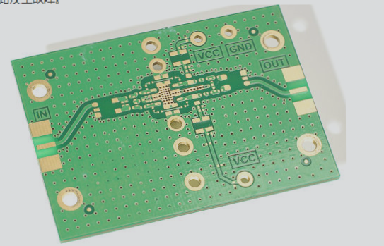
Internal Circuit Board Structure
The circuit board of an air conditioner, known as a PCB, is located within the indoor unit. Some air conditioners may also have circuit boards in the outdoor unit. Certain models have multiple interconnected circuit boards within the indoor unit.
Single Board Circuit Air Conditioner
A single-board circuit air conditioner contains a primary circuit board housing various circuits such as the CPU control circuit, power circuit, and airflow direction control circuit. Additionally, there is a small circuit board for indicator lights and remote control functions.

Double Board Circuit Air Conditioner
The dual-board circuit consists of a control circuit board and a power supply board interconnected to deliver power and control signals.
Remote Control and Indication PCB
Standard air conditioners have a separate circuit board for remote control and indication functions, including a remote control receiver and LED indicators for various statuses.
Air Conditioner PCB with Display Screen
Certain air conditioner models feature display screens integrated into the control and display boards, showcasing LED digital tube displays, LCDs, or VFD options.
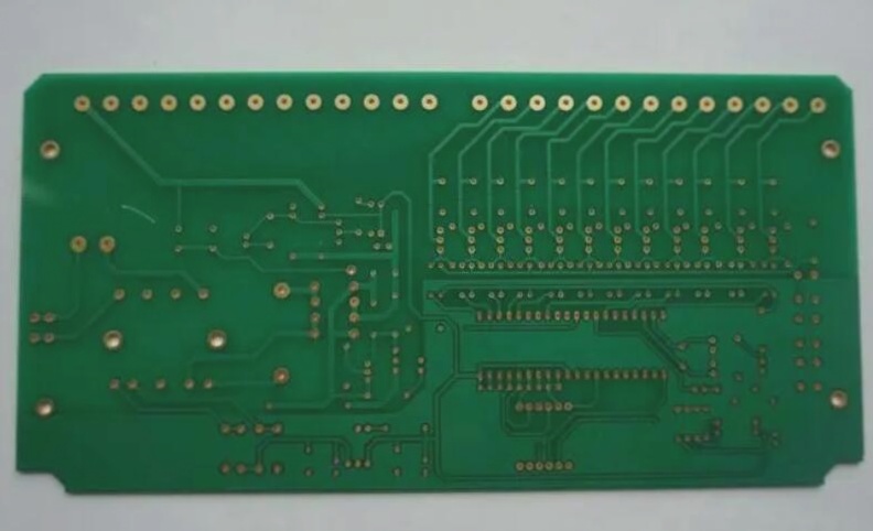
External Circuit Board Structure
In addition to the internal circuit board, the external unit has a circuit board based on the control circuit’s structure.
Two Routing Methods for Circuit Boards
Electronic products rely on circuit boards for functionality. A PCB expert explains two wiring methods used in circuit board production.
The First Method: Manual Wiring
Level and size the circuit board correctly, place components, manually route connections based on the schematic diagram, and make necessary modifications for superior results.
The Second Method: Automatic Wiring
The PCB Design Process: A Comprehensive Guide
Embarking on a PCB design journey involves several crucial steps to ensure a successful outcome. Let’s delve into the intricacies of the process:
Step 1: Schematic Design
- Utilize a schematic editor to create the schematic and perform an electrical check (ERC).
- Generate a netlist that serves as the blueprint for the circuit connections.
Step 2: PCB Configuration
- Transition to the PCB environment and utilize the circuit wizard tool.
- Specify the board’s parameters, including layer count and dimensions.
Step 3: Netlist Integration
- Load the netlist via the Design/Netlist menu, ensuring compatibility with the component library.
- Vigilantly address any discrepancies to avoid errors during the design process.
Step 4: Component Placement
- Arrange components logically on the board, either manually or through automated tools.
- Iterate on the layout to achieve optimal positioning and connectivity.
Step 5: Routing and Wiring
- Establish routing rules and initiate automatic wiring to streamline the connection process.
- Balance between automated efficiency and manual precision for optimal results.
Step 6: Finalization and Saving
- Make final adjustments to the design and choose to save the file or proceed with printing.
When it comes to wiring methods, automatic routing offers convenience but may not always match the meticulousness of manual techniques. Each approach presents unique benefits, with the selection often tailored to the project’s specific demands.
If you require PCB manufacturing services or have any inquiries, feel free to reach out to us. We’re here to bring your PCB designs to life.