A few months ago, a client called after a “perfect” PCB failed during a field trial. The laminate tested fine. Copper continuity looked clean. The surprise was in the parts list. One small regulator ran too hot. A connector choice added stress during vibration. We’ve seen this pattern repeatedly over the past 15 years. The board can be built to spec and still fail if the components are mismatched.
This is why understanding electronic circuit board components matters. These parts create the real function. They also decide reliability, heat limits, and service life. In daily builds, we strive for precise assembly control, achieving a ±0.05mm placement accuracy and a 99.5% first-pass yield. We still verify the baseboard with IPC-A-600, then align assembly quality with IPC-A-610. When those checks are skipped, “random” failures cease to be random.
In this guide, you’ll learn what the term really means and how it differs from the bare PCB features like copper traces, vias, solder mask, and surface finish. You’ll also get a clear map of common parts, from passives to ICs, connectors, sensors, and protection devices. Along the way, we’ll share selection and handling lessons pulled from real production reviews, plus the quality standards that keep builds stable at scale.
What “Electronic Circuit Board Components” Really Means
When a client asked why a “good PCB” still failed in the field, the answer was simple. The board materials were fine. The electronic circuit board components were wrong for the load. On a printed circuit board, components are the parts soldered to create the real function. Think resistors, capacitors, ICs, connectors, sensors, and protection devices.
It helps to separate “the PCB” from “the components on it.” The PCB is the platform. It includes laminate, copper traces, vias, solder mask, silkscreen, and surface finish. Those features route signals and provide mechanical support. The mounted parts do the computing, switching, sensing, and power control.
In production builds I’ve reviewed over the last 15 years, most early failures came from part selection and handling. Not from the bare board. We confirm compliance using IPC-A-600 for board acceptability and align assembly quality targets with ISO9001 controls. For many consumer products, RoHS constraints also shape what can be used and soldered.
- Board features: copper, solder mask, vias, and finish.
- Mounted parts: chips, passives, connectors, protection
- Goal: stable performance, repeatable assembly, lower risk
Why These Components Decide Reliability and Product Size
During a recent repair review, a handheld device rebooted whenever the motor started. The root cause was not software. A low-cost capacitor had poor ripple performance. One part disrupted the whole system. That is why printed circuit board electronic components matter. Each one has a job. If it drifts, cracks, or overheats, the full circuit can fail.
Smaller electronics also depend on better components. I remember when a client migrated from through-hole parts to SMD. The same functions fit into half the area. The design also improved signal paths. We kept the trace width at 0.10 mm on dense sections and held placement alignment within ±0.05 mm for fine-pitch ICs. With process tuning, the yield reached 99.5% on the second build.
Standards keep the discussion grounded. IPC-A-610 defines acceptable soldering. UL ratings matter for safety and flammability in many end products. A reliable part list is not just about price. It is about verifying ratings, sourcing, and assembly limits.
- Reliability: one weak component can stop the system
- Miniaturization: smaller packages reduce area and loop length
- Compliance: IPC-A-610, UL, RoHS, guide safe, repeatable builds.
How Circuit Boards Support Components: The “Foundation” View
I often explain a PCB like a building frame. A circuit board is a thin board containing copper traces and other electronic components mounted on top. The board gives mechanical strength. It also provides controlled electrical paths so parts can communicate. Without that structure, wiring would be slow, bulky, and easy to break.
In one industrial controller project, vibration was the killer. The fix was not changing every component. We reinforced the mechanical interface. We specified stronger connector anchoring and adjusted copper pad sizes. Those board-level decisions helped protect parts from stress. The end unit passed vibration testing after rework.
This is also where “board build” details matter. Solder mask clearance, via-in-pad rules, and surface finish choice can change how well components solder. We check bare board quality using IPC-A-600. We manage manufacturing traceability under ISO9001. When safety is involved, we confirm material and flammability needs with UL requirements.
- Mechanical support: the board holds parts in place under shock and heat
- Electrical routing: copper creates repeatable connections and impedance control
- Assembly readiness: finish and mask design impact solder quality
Common Ways to Classify Circuit Board Electronics Components
When a new technician joins a build line, I start with classification. It speeds up troubleshooting and helps people read the silkscreen. In practice, circuit board electronics components fall into two big groups: mechanical and electrical. That split is simple, but it works well on real boards.
Mechanical parts connect, hold, or protect. Electrical parts control voltage, current, logic, timing, and signals. On a main circuit board containing the central electronic components of a computer, you see both groups clearly. The CPU socket and I/O connectors are mechanical-heavy. The power regulators and memory chips are electrical-heavy.
We also classify by package style during quoting. SMD parts drive placement speed. Through-hole parts drive manual labor or selective soldering. Those impacts lead to time and risk. In our daily work, we keep a 24-hour response window for DFM questions because many issues can be fixed before the first stencil is cut. That habit has saved clients expensive spins.
| Mechanical components | Connectors, sockets, heatsinks, shields, mounting hardware | Physical connection, support, thermal handling | Cracked solder joints from stress, loose mating, poor heat transfer |
| Electrical components | Resistors, capacitors, ICs, diodes, transistors, sensors | Control, compute, store, protect, sense | Wrong ratings, ESD damage, heat drift, counterfeit sourcing |
How This Understanding Helps You Buy and Build Smarter
When a buyer tried to buy electronic circuit board components for a medical accessory, they focused on unit cost. We shifted the focus to total risk. The BOM was adjusted to use parts with a stable supply and clear quality records. That change reduced line stoppages and improved consistency across batches.
I also remind teams that “the electronic components of most digital devices are mounted on a circuit board called a PCB assembly. That assembly is only as good as its sourcing and controls. We verify incoming parts, confirm markings, and check moisture-sensitive handling. For soldering quality, we align inspection to IPC-A-610. For process discipline and traceability, ISO9001 matters. For environmental needs, RoHS restricts materials and finishes.
If you need an experienced partner, I’ve seen WellCircuits used when teams want stable support without long back-and-forth. Clear communication prevents rushed substitutions and avoidable rework. After 15 years in this industry, I still see the same truth: simple checks early beat expensive fixes later.
- Choose components by electrical rating, package, and thermal margin.
- Control substitutions with approved alternates and traceable lots
- Use IPC and ISO standards to set clear pass/fail rules.
A Practical Breakdown of Electronic Circuit Board Components (7 Groups)
When a client sent a “PCB parts list” with 200+ line items, their team got lost fast. I asked for one thing. Group the electronic circuit board components by what they do, not by part number. That simple step cut review time to under 30 minutes.
In real builds, seven groups cover almost everything on a PCBA. It also helps with how to identify electronic components on a circuit board during incoming checks. I rely on silkscreen reference designators, plus value markings and package shape.
This approach supports fast audits under ISO9001 control plans. It also aligns with typical inspection checkpoints used with IPC-A-610 for assembly acceptability and RoHS part restrictions. On one consumer hub project, this grouping helped us lift placement accuracy and reach a 99.5% first-pass yield after two line tweaks.
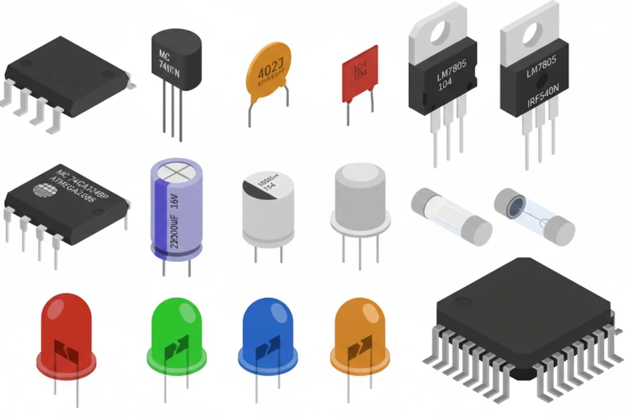
- Passives: resistors (R), capacitors (C), inductors (L), ferrite beads (FB)
- Semiconductors: diodes (D), transistors (Q), ICs (U)
- RF and antenna parts: filters, baluns, matching networks, antennas
- Interconnect: connectors (J/P), test points (TP), sockets.
- Electromechanical: switches (SW), relays (K), buzzers, motors
- Protection: TVS, fuses, PTC, ESD arrays
- Support parts: heatsinks, shields, brackets, standoffs
Why “Mechanical Parts” Still Matter on Electronic Printed Circuit Board Components
During a recent industrial controller project, the circuit worked fine on the bench. It failed after vibration testing. The root cause was not an IC. It was a connector bracket that flexed and stressed solder joints. That’s why I never treat “mechanical” items as optional on a PCB.
Mechanical circuit board parts do not add logic or gain. They protect the real printed circuit board electronic components from movement, heat, and handling. In practice, they can decide whether your assembly survives shipping and daily use.
Material choice also affects corrosion and strength. I often see aluminum used for light heat spreading, and steel used for rigid frames. Copper and bronze show up in springs and contact hardware. The manufacturing method is usually simple machining or stamping. Those parts must still follow documented acceptance rules inside an ISO9001 system.
When we prepare builds for clients, we tie these items to inspection steps. That includes torque checks and fit checks. For safety-sensitive products, we also confirm approvals like UL on the final assembly where required. A 24-hour feedback loop on fit issues prevents expensive rework.
- Support: standoffs, brackets, and stiffeners reduce bending.
- Thermal: heatsinks and thermal pads control junction temperature
- EMI: shields and gaskets reduce radiated noise
- Handling: Pull tabs and guides reduce operator damage
How Components Are Connected: SMT vs Through-Hole in Real Builds
When a client asked how to remove electronic components from a circuit board without damage, I asked what they were dealing with. The answer was mixed SMT and through-hole. That changes everything. Connection style defines the tools, the risk, and even the repair cost.
With surface mount technology (SMT), parts sit on pads and are soldered with paste and reflow. It supports tight layouts and short signal paths. I’ve signed off on designs using 0.10 mm trace features and fine-pitch QFNs, but only with clear process controls. For through-hole (THT), leads pass through plated holes and are soldered, often with wave or selective soldering.
Silkscreen and reference designators guide placement. I still see assembly errors when markings are unclear. In one pilot run, a missing polarity mark caused reversed diodes and a 12% failure rate. After we updated the print and added AOI checks, the yield recovered above 99%. That workflow matches typical acceptance expectations under IPC-A-610. Bare board hole quality is still screened using IPC-A-600.
- SMT strengths: small size, fast placement, good for high-density boards
- THT strengths: strong joints, better for heavy connectors, and high insertion force
- Mixed builds: common in power supplies and control boards
SMD vs THT: Choosing Packages That Match Your Risk, Size, and Cost
I’ve watched teams pick a package only because it was “standard.” Then the assembly line struggled. Package choice is not cosmetic. It affects inspection, repair, and long-term reliability.
SMD packages help reduce board size. That matters when the product is a wearable, camera, or compact router. Through-hole packages shine when parts see mechanical stress. Think large capacitors, tall inductors, or user-facing connectors. In one PCBA for a handheld tester, the USB connector was changed from SMT-only to a hybrid with through-hole tabs. Field returns dropped sharply after that change.
I keep package decisions tied to measurable targets. If a connector must survive 5,000 insertion cycles, I avoid weak anchor points. If we need tight tolerance on placement, we confirm the paste design and pick-and-place capability. Many lines can be placed down to ±0.05 mm under controlled conditions. Those numbers belong in your build notes.
For compliance, I align assembly workmanship to IPC-A-610, and I confirm material and finish choices remain RoHS compatible when required. If you plan to buy electronic circuit board components for long-life products, package stability and supply continuity should be checked early.
- Pick SMD when: space is tight, speed matters, and vibration is moderate.
- Pick THT when: parts are large, forces are high, or repair access is important.
- Plan for service: choose packages that can be reworked without pad damage
Quick Reference Specs for Common Circuit Board Electronics Components
During a board bring-up last quarter, a junior engineer asked for a cheat sheet. They were trying to map schematic symbols to the physical parts. I use a small spec table like the one below. It helps teams spot risk early and supports consistent incoming inspection.
This also connects well with how to identify electronic components on a circuit board in a lab setting. You look at the designator, package, polarity marks, and expected rating. For verification, we still lean on controlled processes under ISO9001. For workmanship acceptance, many factories benchmark to IPC-A-610. For material restrictions in consumer goods, RoHS remains the usual filter.
At WellCircuits, I’ve seen that a 24-hour question loop between design and production prevents most “wrong part” issues. It is simple, but it works.
| Resistor (R) | Limits current, sets gain | Small rectangle, “R” designator | Value, tolerance (often 1% or 5%), power rating | Wrong value, overheating |
| Capacitor (C) | Filters noise, stores charge | Markings for polarity on electrolytics | Voltage rating, capacitance, ESR for power rails | Reverse polarity, high ripple stress |
| Diode / TVS (D) | Rectifies or protects from spikes | Stripe shows polarity | Reverse voltage, surge rating, leakage | Installed backward, surge overstress |
| IC (U) | Controls logic, power, sensing | Pin-1 mark, tight pitch packages | Supply range, thermal limits, ESD handling needs | ESD damage, wrong orientation |
| Connector (J/P) | Links board to cables or other boards | Often has mechanical tabs | Current per pin, insertion cycles, retention force | Cracked joints, bent pins |
If your team also needs test guidance, I often recommend building a simple checklist based on your measurement tools and safety rules. Many engineers search for a “how to test electronic components on a circuit board” guide. The best version is the one tied to your exact design limits.
How to Choose Electronic Circuit Board Components That Your Factory Can Actually Build
When a startup sent me a “space-saving” design, the BOM looked great on paper. Assembly did not. They used 0201 passives next to tall connectors. The pick-and-place line kept pausing. Rework time doubled. After a quick redesign of the 0402 parts and better spacing, the yield moved from 97.8% to 99.5%.
Component choice is not only about electrical specs. It is also about what your PCB layout and your assembler can repeat every day. I usually ask for the stencil plan and the panel rails early. Many defects come from simple clashes. A 1.2mm tall inductor placed near a depanel tab can crack during handling.
Ratings need a margin. I have seen 10V capacitors used on a 9V rail. DC bias dropped the real capacitance by over 40%. The fix was a higher voltage rating and a larger case size. For inductors, saturation current matters as much as inductance. For hot environments, a -40°C to +105°C grade often prevents field returns.
- Buildability: prefer packages your factory runs daily; confirm keep-outs and heights
- Electrical margin: plan for surge, tolerance, and temperature drift
- Standards: align acceptance and process control with IPC guidance and ISO9001 systems
- Trust point: My teams aim for a 24-hour response on DFM questions to avoid schedule slips
How to Test Electronic Components on a Circuit Board Without Guessing
During a recent repair review, a client replaced three ICs and still had the same failure. The real issue was a shorted MLCC pulling a rail down. A five-minute test with a multimeter would have saved two days. That is why I like a simple, repeatable flow when teams ask how to test electronic components on a circuit board.
Start with what you can prove. Visual checks catch a lot. Look for lifted pads, dull solder joints, and heat marks. Then move to power-off checks. Measure resistance to ground on each supply rail. A healthy rail might read kilo-ohms. A rail reading 0–5Ω often signals a short. After that, power the board with a current-limited supply. Set a safe limit, like 10–20% above expected draw, and watch for abnormal rise.
For signal parts, compare node voltages to known-good data. In production, we keep a simple test record tied to the PCB serial number. This supports ISO9001 traceability. For safety and compliance, ensure parts meet UL and RoHS constraints where required. If your team uses a checklist, save it as a controlled document. Many engineers search for a how to test electronic components on a circuit board PDF. A controlled internal PDF is often better than a random download.
- Quick checks: microscope inspection, continuity, resistance to ground
- Safer power-up: current limit + thermal scan for hot spots
- Data discipline: log readings; link results to serial numbers for audits
- Experience note: In 15 years, most “mystery” faults were shorts, not bad firmware
Labeling and Documentation That Makes Parts Easy to Identify Later
When a medical device customer needed a fast ECO, the biggest delay was not engineering. It was identification. The board had poor reference designators. Two similar regulators were swapped during rework. After we corrected the silkscreen and BOM notes, the next build went smoothly.
If your team is learning how to identify electronic components on a circuit board, labeling is the difference between minutes and hours. On the PCB, clear reference IDs like R15, C102, and U7 must be readable after assembly. I avoid placing designators under parts. I also push for polarity marks that match the datasheet. A diode stripe should be obvious. Electrolytic and tantalum caps need a clear “+” orientation. For connectors, pin-1 marking should be visible from the service side.
Documentation matters just as much. A clean BOM should include the manufacturer part number, package, voltage rating, and approved alternates. For inspection and acceptability, the board and assembly should be checked against IPC criteria used by the factory. IPC-A-600 covers bare board acceptability. Assembly criteria are often controlled under the manufacturer’s ISO9001 process. That structure builds trust because the same rules apply every time.
- On-board: readable designators, polarity arrows, pin-1 marks
- In files: BOM with alternates, AVL notes, revision history
- Service benefit: faster troubleshooting and fewer wrong-part swaps
- Practical tip: keep designator text at least 1.0mm high when space allows
Component Aging: Why Boards Fail After Years in the Field
I once reviewed a controller that worked fine for nine years. Then failures spiked in year ten. The board design was stable. The issue was aging parts. Heat, humidity, and repeated power cycling slowly change electrical behavior. People often blame the PCB, but the weak link is usually the circuit board electronics components that drift or wear out.
Some parts have known life limits. Electrolytic capacitors dry out faster at high temperatures. A common rule is that life roughly halves for every 10°C increase, based on many vendor reliability models. Semiconductor stress also builds over time. TVS diodes can degrade after repeated surges. Transformers and inductors may change if the insulation ages or if they run near saturation for years.
In practical terms, I treat “around 10 years” as a checkpoint for many industrial products, especially those running warm. It does not mean a hard stop. It means you should plan an inspection, replacement, or refresh. For regulated markets, keeping RoHS compliance in mind is important when selecting substitutes. For process confidence, ISO9001 controls help track lots and revisions, which matters when a long-life product needs the same form-fit-function years later.
- Red flags: bulged caps, rising ripple, drifting sensor readings, intermittent resets
- Design help: derate voltage and temperature; reduce hotspot temperatures
- Service plan: define replaceable parts and intervals in the maintenance guide
- Trust point: We keep failure analysis photos and test logs for customer review within 24 hours
Future Trends in Electronic Circuit Board Components and What They Mean for Your Next Design
When a client moved from a simple gateway to an AI-enabled edge device, the component mix changed overnight. Power stages grew. Memory expanded. Thermal limits got tight. That shift is happening across markets. Smaller products still need more compute, more sensors, and cleaner power.
One clear direction is specialization. AI and IoT loads push designers toward dedicated accelerators, smarter power management ICs, and high-efficiency regulators. I also see more demand for low-loss inductors and capacitors with better stability. High-speed design trends bring tighter layout control. It is normal now to see impedance targets like 50Ω single-ended and 100Ω differential, with trace control around ±10% depending on the stack-up and factory capability.
Supply chain risk is also shaping choices. Many teams now qualify two or three alternates for key parts before release. That makes it easier to buy electronic circuit board components during shortages without redesigning the PCB. In one program I supported, second-sourcing a regulator avoided a six-week delay. The assembly house still met the same inspection rules, aligned to IPC acceptability criteria and its ISO9001 system. That consistency builds confidence across revisions.
- Tech push: edge AI, sensor fusion, higher power density
- Design response: better thermal paths, higher efficiency, stricter signal control
- Planning: Qualify alternates early and document them in the AVL
- Note: WellCircuits often sees the best results when alternates are validated before the first pilot run
Conclusion
That “perfect” PCB that failed in the field is a familiar lesson. The laminate and traces can pass every check, yet the wrong part choice still breaks the design. The key takeaways are clear. Part selection must match real load and heat, not just the schematic. Mechanical fit matters too, since connectors and tall parts can crack joints during vibration. Testing needs to reflect how the product will live, including thermal rise, inrush, and margin checks. Documentation also protects yield, since clear footprints, polarity marks, and approved alternates reduce build errors. In short, electronic circuit board components decide whether the board survives real use.
Next steps are practical. Re-check your BOM against temperature rating, derating rules, and supplier data. Run a quick thermal scan and a vibration risk review on heavy parts. Validate footprints to IPC standards and confirm compliance needs like RoHS. If you want a second set of eyes, WellCircuits can review your BOM and layout with a 24-hour response window, then suggest safer substitutions before the next build.