What Is Copper Clad Laminate (CCL)?
When people say “PCB board,” they’re usually talking about a copper clad laminate at its core. A copper clad laminate (CCL) is a flat PCB substrate material made by bonding thin copper foil to one or both sides of an insulated base. That base is typically a glass fiber reinforced laminate (like FR4 laminate) or a flexible film such as polyimide.
In simple terms, a copper clad board is the starting sheet we use to manufacture printed circuit boards. Every trace, pad, and plane you see in a finished PCB begins as copper on this laminate.
Core Composition of Copper Clad Laminate
A quality copper clad laminate sheet is always a combination of four core elements:
- Substrate / Base Material
- Common rigid options: FR4 copper clad laminate, CEM-1, CEM-3
- Flexible options: polyimide copper clad laminate, PET-based flexible CCL
- Defines electrical, thermal, and mechanical behavior
- Resin System
- Typically epoxy resin laminate for standard FR4
- Advanced systems: high Tg copper clad laminate, halogen-free resin, low-loss resin
- Controls dielectric constant, loss tangent, heat resistance, and reliability
- Reinforcement
- Usually woven glass cloth in rigid CCL
- Can be glass-free (for special RF or flexible materials)
- Delivers stiffness, dimensional stability, and strength
- Copper Foil
- Electro-deposited (ED) or rolled-annealed (RA) copper
- Thickness ranges from 9 μm to 105 μm and beyond
- Forms the conductive layers in the copper clad laminate PCB
These elements are precisely combined and laminated to create a stable, repeatable PCB base material suitable for mass production.
Single-Sided vs Double-Sided Copper Clad Laminates
When you’re sourcing or specifying copper clad laminate (CCL), one of the first decisions is simple: single-sided or double-sided?
- Single-Sided Copper Clad Laminate
- Copper on one side of the insulating substrate
- Used in simple, low-cost circuits: power supplies, LED modules, consumer appliances
- Easier etching and drilling, ideal for basic designs and cost-sensitive projects
- Double-Sided Copper Clad Laminate
- Copper on both sides of the substrate
- Enables via holes, ground planes, better routing density
- Standard choice for most copper clad laminate PCB designs in the US market
The choice directly affects routing flexibility, signal integrity, and total PCB cost.
How CCL Provides Conductivity, Insulation, and Support
Every PCB has to do three things well: conduct signals, insulate safely, and stay mechanically stable. A well-designed CCL copper clad laminate delivers all three:
- Conductivity
- The copper foil forms traces, pads, planes, and power rails
- Low-resistance copper ensures clean signal transmission and power delivery
- Insulation
- The resin + substrate matrix acts as a high-resistance insulator
- Controls leakage current, creepage distance, and breakdown voltage
- Key for safety-critical designs and RoHS-compliant electronics
- Mechanical Support
- The glass fiber reinforced laminate resists warpage, cracking, and vibration
- Holds components, vias, and copper together through soldering and thermal cycling
- A stable rigid copper clad board or flexible FCCL underpins long-term reliability
As a PCB and laminate partner, I look at CCL as the foundation of the entire electronics stack. If the copper clad laminate is wrong, everything that follows—signal quality, assembly yield, product lifetime—pays the price.
Main Types of Copper Clad Laminate (CCL)
When I pick copper clad laminate for a PCB project in the U.S., I usually group it into four buckets: rigid CCL, flexible CCL, high-frequency CCL, and special CCL. Each one fits a different job.
Rigid Copper Clad Laminate: FR4, CEM-1, CEM-3
Rigid copper clad boards are the default PCB base material for most electronics.
Common rigid CCL types:
- FR4 copper clad laminate
- Glass fiber reinforced epoxy resin laminate
- Best mix of cost, strength, and electrical performance
- Used in: laptops, servers, consumer electronics, industrial controls
- CEM-1
- Paper + epoxy resin, single-sided copper clad laminate sheet
- Lower cost, lower mechanical strength than FR4
- Used in: low-cost power boards, adapters, simple household products
- CEM-3
- Glass + epoxy, similar to FR4 but easier drilling, smoother surface
- Used in: consumer PCBs, LED driver boards, white goods
Flexible Copper Clad Laminate (FCCL) & Polyimide Laminates
When space is tight and boards need to bend, I move to flexible CCL.
Main flexible CCL options:
- Polyimide flexible copper clad laminate (polyimide FCCL)
- Thin, bendable, high heat resistance
- Used in: smartphones, wearables, foldable devices, cameras
- Adhesive-based vs. adhesive-less FCCL
- Adhesive-less gives better high-speed and flex reliability
- Great for compact, high-density U.S. electronics
Brands like Pyralux LF copper clad laminate are popular for high-reliability flex circuits.
High-Frequency & High-Performance CCL (Low-Loss, Halogen-Free, Lead-Free)
For 5G, RF, and high-speed digital, I prioritize low-loss CCL and clean materials.
Key features I look for:
- Low dielectric constant (Dk) and low loss tangent (Df)
- Better signal integrity at high GHz
- Halogen-free CCL
- Lower toxic emissions, aligns with green electronics and U.S. compliance trends
- Lead-free copper clad laminate
- RoHS compliant, compatible with lead-free soldering profiles
These high-frequency CCL materials show up in 5G PCB materials, routers, base stations, AI servers, and data center boards.
Special Copper Clad Laminates: Metal Core & PTFE RF
For thermal management and RF, I often switch to special CCL types:
- Metal core CCL / aluminum base CCL
- Aluminum-backed copper clad board
- High thermal conductivity laminate for LED lighting, power supplies, EV chargers
- Copper base CCL
- Even better heat spreading for high-power density boards
- PTFE copper clad laminate (PTFE RF laminates)
- Very low-loss CCL for microwave, radar, RF front-ends
- Common in defense, aerospace, 5G antennas, telecom
These substrates are key when heat and RF performance matter more than cost.
Quick Comparison of Copper Clad Laminate Types
| CCL Type | Core Material System | Key Strengths | Typical Uses (US Market) |
|---|---|---|---|
| FR4 copper clad laminate | Glass cloth + epoxy resin | Balanced cost, strength, good all-around | Consumer electronics, computers, industrial controls |
| CEM-1 / CEM-3 | Paper or glass + epoxy | Lower cost, simpler boards | Low-cost power boards, appliances |
| Flexible copper clad laminate | Polyimide or polyester + copper | Bendable, thin, light | Smartphones, wearables, FPC in laptops and cameras |
| High-frequency CCL | Modified epoxy, PPE, PTFE, etc. | Low-loss, stable dielectric constant CCL | 5G PCB, RF modules, high-speed digital boards |
| Metal core / aluminum base CCL | Aluminum or copper + dielectric | High thermal conductivity, strong | LED lighting, EV power electronics, BMS, chargers |
| PTFE RF laminate | PTFE + glass or ceramic filler | Ultra-low loss, high-frequency RF performance | RF, microwave, radar, satellite, telecom infrastructure |
I design and source copper clad laminate based on signal speed, operating temperature, mechanical needs, and budget. Matching the right CCL type to the application is what keeps PCB reliability and performance high in real U.S. use cases.
How Copper Clad Laminate Is Manufactured
Raw materials for copper clad laminate (CCL)
To build a stable, repeatable PCB base material, I always start with tight control of the core ingredients:
- Glass cloth (fiberglass) – forms the glass fiber reinforced laminate backbone for FR4 and most rigid copper clad boards. It gives mechanical strength and dimensional stability.
- Epoxy resin or specialty resin systems – binds the glass cloth and defines key properties like Tg, dielectric constant, and thermal performance. For high-frequency CCL, I’ll switch to low-loss resins or PTFE.
- Copper foil – high-purity electrolytic or rolled copper in different thicknesses (like 1 oz, 0.5 oz). Surface treatment on the copper side is critical for peel strength and low loss.
For the U.S. market, I lean on RoHS compliant, halogen-free CCL, and lead-free copper clad laminate options to meet eco and regulatory expectations.
Prepreg sheet production and resin impregnation
The heart of the CCL manufacturing process is prepreg:
- I run glass cloth through a resin bath where epoxy resin or other PCB laminate materials fully impregnate the fibers.
- Then it’s partially dried (B-stage) to form prepreg sheets — solid, tack-free, but still meltable under heat and pressure.
- Different resin content and glass styles let me tune rigidity, dielectric performance, and thickness for each PCB substrate material stackup.
This is where we dial in consistency so downstream PCB shops in the U.S. see predictable lamination behavior and minimal warpage.
Layup, high-pressure lamination, and curing
Next, I stack everything to build the actual copper clad laminate sheet:
- Layup: alternate layers of prepreg and copper foil in a clean environment, based on the target thickness and type (FR4 copper clad laminate, high Tg laminate, etc.).
- High-pressure lamination: apply controlled heat, pressure, and time so the resin flows, fills voids, and bonds the copper foil to the glass cloth.
- Curing: hold at temperature to fully cure the resin system, locking in mechanical, electrical, and thermal properties.
Well-controlled lamination and curing of CCL is key to avoiding delamination, voids, and warpage later in PCB fabrication and assembly.
Inline quality control and testing
For U.S. customers running high-volume copper clad laminate PCB production, quality must be predictable:
- Visual and dimensional checks – thickness, flatness, surface quality, and copper roughness.
- Electrical tests – dielectric constant (Dk), loss tangent (Df), insulation resistance, and breakdown voltage for high-speed and RF applications.
- Mechanical tests – peel strength, flexural strength, and dimensional stability.
- Thermal tests – Tg, CTE, and heat resistance for reflow and high-temperature environments (automotive, power, data center).
I build these inline quality control steps into the line so each CCL lot supports high PCB yields and long-term reliability.
Environmental and sustainability in CCL production
In the U.S. market, eco compliance isn’t optional—it’s part of the business model:
- Use low-VOC and optimized resin systems to cut emissions.
- Offer halogen-free CCL, lead-free copper clad laminate, and RoHS compliant laminate to support green electronics.
- Improve energy efficiency in lamination, curing, and drying processes.
- Recycle copper scrap and manage wastewater and chemical treatment to meet local environmental rules.
I’m pushing toward sustainable CCL production so OEMs and PCB manufacturers can hit their ESG goals without sacrificing performance or cost.
Copper clad laminate properties and performance
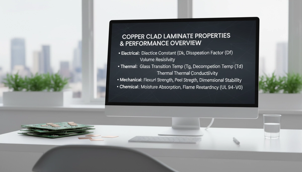
When I pick a copper clad laminate (CCL) for a PCB build, I’m really looking at four pillars: electrical, thermal, mechanical, and safety/compliance. If any one of these is off, long‑term reliability drops fast, especially in US markets like automotive, networking, and data centers.
Electrical properties of copper clad laminate
For signal integrity and low noise, the electrical specs matter a lot:
- Dielectric constant (Dk)
- Controls trace impedance and signal speed.
- High‑speed and RF boards need stable, low Dk across frequency and temperature.
- FR4 copper clad laminate works for most consumer boards; low-loss CCL and PTFE laminate for RF are better for 5G, Wi‑Fi 6/7, and high‑speed digital.
- Loss tangent (Df)
- Directly tied to insertion loss on high-speed lines.
- For 10G/25G/56G+ designs, I look for low-loss CCL with very low Df.
- Insulation resistance and breakdown voltage
- Keeps high-voltage and dense layouts safe.
- Critical in EV BMS, power supplies, and automotive PCB laminate.
Thermal performance of CCL
Thermal behavior decides how well the board survives real-world heat cycles:
- Tg (glass transition temperature)
- Above Tg, the laminate softens and expands more.
- For US automotive, industrial, and server boards, I typically specify high Tg copper clad laminate (≥ 150–170 °C).
- CTE (coefficient of thermal expansion)
- Needs to be matched to copper to reduce via cracking and pad lifting.
- Good glass fiber reinforced laminate and filled systems keep CTE under control.
- Heat dissipation & thermal conductivity
- For power electronics, LEDs, and EV inverters, I lean on metal core CCL, aluminum base CCL, or copper base CCL as a thermal conductivity laminate to move heat away from hot spots.
Mechanical strength and reliability
Mechanical performance drives yield and field reliability:
- Peel strength
- Measures how strongly copper foil bonds to the resin system.
- Strong peel strength helps avoid pad lifting during rework and reflow.
- Dimensional stability
- Impacts layer registration, impedance control, and fine‑pitch designs.
- Critical for HDI, rigid copper clad board, and tight stackups in smartphones and networking gear.
- Warpage and flatness
- Warpage creates assembly issues and BGA solder defects.
- Good lamination and curing of CCL, correct glass style, and balanced stackups cut down on warpage and delamination in CCL.
Safety and compliance: flammability, RoHS, halogen‑free
For the US and global market, I never ignore compliance:
- Flammability ratings
- Most PCB laminate materials target UL94 V‑0 for safety in consumer electronics, automotive, and telecom.
- RoHS compliant laminate & lead-free CCL
- Must handle lead‑free reflow profiles (up to ~260 °C) without delamination.
- I always choose RoHS compliant, lead-free copper clad laminate for export-ready products.
- Halogen-free CCL and eco-friendly PCB materials
- Many US OEMs now ask for halogen-free CCL and more sustainable CCL production.
- This covers lower halogen content, reduced emissions, and cleaner resin systems without sacrificing performance.
If I boil it down: strong electrical performance, stable thermal and mechanical behavior, and strict safety/compliance are what make a copper clad board reliable over years of real‑world use.
PCB Applications of Copper Clad Laminate (CCL)
Copper clad laminate (CCL) is the base material that makes almost every PCB work. When I choose a CCL for a project in the U.S. market, I’m thinking reliability first, then cost and manufacturability.
Copper Clad Laminate Uses in Consumer Electronics
For consumer electronics, FR4 copper clad laminate and rigid copper clad board still dominate:
- Smartphones & tablets: high-Tg FR4 and low-loss CCL for high‑speed digital, RF front ends, and tight HDI stackups.
- Laptops & PCs: multi-layer FR4 laminate for motherboards, GPUs, SSDs, and power boards.
- Home appliances: cost-effective FR4 and CEM‑1 PCB substrate material for power boards, control panels, and LED drivers.
Here I focus on consistent quality, flatness, and good peel strength, because U.S. brands demand low field failures and strong warranty performance.
Copper Clad Laminate in Automotive PCBs (EV, BMS, ADAS)
Automotive PCBs in the U.S. and North America need tougher CCL:
- EV inverters & onboard chargers: metal core CCL, aluminum base CCL, and high Tg copper clad laminate for thermal management and high voltage isolation.
- Battery management systems (BMS): stable FR4 and low-CTE laminates for long life and accurate sensing.
- ADAS & radar: high-frequency CCL and PTFE laminate for RF for 77 GHz radar and high‑speed data links.
I prioritize AEC‑Q level reliability, thermal conductivity laminate, and tight dimensional stability for these builds.
High-Frequency CCL for 5G and Telecom
For telecom, 5G, and data links, we move to low-loss CCL and RF-grade materials:
- 5G base stations and small cells: PTFE copper clad laminate, hydrocarbon/ceramic low‑loss CCL, and halogen-free CCL for antenna arrays and RF modules.
- High‑speed backplanes & routers: low dielectric constant CCL and stable loss tangent for 25G/56G/112G signaling.
- Microwave links: PTFE RF laminates and hybrid stackups (FR4 + RF laminate) to balance cost and performance.
Here the target is signal integrity, low insertion loss, and controlled impedance across frequency and temperature.
Aerospace, Defense, and Medical PCB Applications
In aerospace, defense, and medical, copper clad laminate has to be mission-grade:
- Avionics & radar: high‑reliability FR4, PTFE RF laminates, and copper base CCL with excellent dimensional stability.
- Defense systems: low-loss, high‑frequency CCL and glass fiber reinforced laminate for rugged environments.
- Medical devices: RoHS compliant laminate, lead‑free copper clad laminate, and halogen-free CCL for imaging, monitoring, and implant-adjacent devices.
I look for tight QC, full traceability, and stable supply from top copper clad laminate manufacturers and brands like Panasonic where needed.
Emerging Applications: High‑Speed Digital, IoT, AI Servers, Data Centers
New U.S. applications are pushing CCL harder than ever:
- High‑speed digital & AI servers: low-loss, low Dk/Df CCL for PCIe 5.0/6.0, DDR5, and ultra‑high‑speed links in servers and switches.
- Data centers: high-reliability FR4 plus high‑speed digital PCB laminate for dense backplanes and high-current power delivery.
- IoT devices & wearables: flexible copper clad laminate (FCCL) and polyimide copper clad laminate for thin, bendable PCBs and antennas.
When I spec materials here, I balance performance, cost, and volume manufacturability, making sure the copper clad laminate PCB stackup is realistic for U.S. and offshore fab partners.
How to choose the right copper clad laminate (CCL)
Match CCL type to your PCB application
When I pick a copper clad laminate, I always start from the application and work backward:
- Consumer electronics (phones, laptops, home devices)
- Go-to: FR4 copper clad laminate or CEM-1/CEM-3 rigid CCL
- Focus on: cost, stable dielectric constant, decent thermal performance
- Automotive PCBs (EV, BMS, ADAS)
- Use: high Tg copper clad laminate, metal core CCL, or aluminum base CCL for heat
- Focus on: high reliability, low warpage, -40–150°C stability
- 5G, RF, and high-speed digital
- Use: high-frequency CCL, PTFE laminate for RF, low-loss CCL
- Focus on: low dielectric constant (Dk), low loss tangent, tight thickness control
- Power and LED boards
- Use: aluminum base CCL or copper base CCL for thermal conductivity laminate
- Focus on: heat spreading, insulation strength, creepage/clearance
- Flexible designs (wearables, foldable, compact IoT)
- Use: flexible copper clad laminate (FCCL), polyimide FCCL, Pyralux-type materials
- Focus on: bend radius, flex cycles, adhesive vs adhesive-less stackups
Balance cost, reliability, and manufacturability
For U.S. builds, I balance performance vs total cost of ownership, not just laminate price:
- Cost
- FR4 laminate is still the best value for standard boards
- High-frequency CCL and PTFE laminates cost more but cut signal loss and re-spins
- Reliability
- Look for RoHS compliant laminate, halogen-free CCL, lead-free copper clad laminate with proven field data
- For automotive and industrial, I always spec high Tg and better CTE control
- Manufacturability
- Use PCB substrate material your local PCB shops already run daily
- Confirm: drillability, plating adhesion, solderability, lamination window, and stackup capability
- Ask for the CCL datasheet + PCB fab capability list before locking the material
Avoid common CCL problems: warpage, delamination, poor adhesion
Most failures I see trace back to mismatched materials or poor process control:
- Warpage in copper clad boards
- Choose symmetric stackups and matching PCB laminate materials
- Use proper copper balance on both sides of the rigid copper clad board
- Select CCL with good dimensional stability and controlled CTE
- Delamination
- Use high-quality prepreg sheets and follow the recommended lamination and curing profile
- Avoid overbaking; control moisture before reflow
- Pick epoxy resin laminate or high-performance CCL with solid peel strength data
- Poor adhesion (peel strength issues)
- Use CCL with treated copper foil suited to your surface finish
- Check compatibility of solder mask, plating, and laminate
- Work with the PCB fab to tune roughening and cleaning steps
Work closely with PCB manufacturers and CCL suppliers
To get better stackups and yields in U.S. production, I push for tight collaboration:
- Share your electrical targets (impedance, loss), thermal limits, and lifetime requirements up front
- Ask the PCB shop which copper clad laminate sheet brands (Panasonic, local copper clad laminate manufacturers in India/Asia, etc.) they run with high yields
- Co-design the stackup with the fab and the CCL supplier to lock in:
- Layer count, copper thickness, prepreg types
- Press cycles and lamination temperatures
- For big programs (EV, telecom, AI servers), do sample builds across multiple CCL sources to reduce supply chain risk and stabilize lead times
By taking this approach, you’re not just buying CCL—you’re designing in the right copper clad laminate for your PCB that hits performance, cost, and reliability targets from day one.
Copper clad laminate market trends
Growth drivers for copper clad laminate (CCL)
From what I’m seeing across our U.S. customers, demand for copper clad laminate is being pushed hard by a few clear trends:
- 5G and high-speed digital: 5G base stations, routers, and AI servers need low-loss CCL, tight dielectric constant control, and stable performance up to mmWave. That’s boosting PTFE copper clad laminate, high-frequency CCL, and advanced FR4 copper clad laminate with better loss performance.
- Miniaturization: Smartphones, wearables, and IoT devices are driving thinner copper clad laminate sheets, high Tg copper clad laminate, and tighter dimensional stability to keep fine-line PCBs reliable.
- Electric vehicles and automotive: EV inverters, on-board chargers, and BMS use metal core CCL, aluminum base CCL, and copper base CCL for heat dissipation, plus high-Tg, high-reliability FR4 laminate for ADAS and powertrain PCBs.
If you’re building for 5G, EV, or high-speed computing in the U.S., the laminate choice is no longer “just FR4” — material performance is now a competitive advantage.
Low-loss and high-frequency copper clad laminate trends
The market is shifting fast toward high-frequency, low-loss copper clad laminates:
- Low-loss CCL with controlled dielectric constant (Dk) and loss tangent (Df) is becoming standard for:
- 5G RF boards
- High-speed digital backplanes
- Server and data center interconnect
- Mix-and-match stackups: Many U.S. OEMs now combine standard FR4 copper clad laminate with PTFE RF laminates or hydrocarbon/ceramic high-frequency CCL in one PCB to balance cost and performance.
- Big brands like Panasonic copper clad laminate and Pyralux LF copper clad laminate (for flex and rigid-flex) are being specified more often in telecom and networking designs.
In short, if your signals are fast, you should be shopping by Dk/Df and insertion loss, not just by “FR4” anymore.
Eco-friendly and sustainable CCL materials
U.S. customers are also asking more about eco-friendly PCB materials and sustainable CCL production:
- Halogen-free CCL and lead-free copper clad laminate to meet RoHS compliant laminate requirements and corporate ESG goals.
- Lower-smoke, low-tox formulations for data centers, medical, and public infrastructure.
- Processes that reduce VOC emissions, wastewater, and scrap in the copper clad laminate manufacturing process.
If your products target large enterprises or export to the EU, specifying halogen-free CCL and clearly labeling RoHS compliance is now almost mandatory.
Global supply chain, lead times, and pricing
The copper clad laminate market is still feeling the impact of global supply shifts:
- Regional diversification: More buyers in the U.S. want dual sourcing across Asia, North America, and copper clad laminate manufacturers in India to cut risk.
- Price drivers:
- Copper price volatility
- Epoxy and resin cost swings
- Energy costs and logistics
- Lead times for specialty high-frequency CCL, flexible copper clad laminate (FCCL), and exotic PTFE laminate for RF can be much longer than for standard rigid copper clad board.
My advice if you’re designing new hardware:
- Lock in copper clad laminate specs early with your PCB fab.
- Confirm HS code / HSN code (for example, copper clad laminate HS code / HSN code 741021 variants) for import planning.
- Get a clear view on copper clad laminate price, MOQ, and lead time before freezing your BOM.
That’s how we help our U.S. clients stabilize cost, avoid last‑minute redesigns, and keep PCB production on schedule.
Copper clad laminate FAQs
CCL vs PCB – what’s the difference?
| Term | What it is | How it’s used |
|---|---|---|
| Copper clad laminate (CCL) | Raw copper clad board: copper foil bonded to an insulating PCB substrate material (FR4, polyimide, PTFE, etc.) | Base material PCB shops drill, image, etch, and plate |
| PCB (printed circuit board) | Finished board with traces, vias, solder mask, silkscreen, surface finish | What goes into your phone, EV, router, server, etc. |
CCL is the starting material. PCB fabrication turns that copper clad laminate sheet into a working circuit.
Why FR4 copper clad laminate is used everywhere
FR4 laminate is the default PCB base material in the U.S. because it hits the best price‑performance balance:
- Low cost and widely stocked by PCB shops
- Good electrical performance for most digital and consumer products
- Decent thermal performance with standard Tg options (130–170°C)
- Stable, rigid mechanical support for SMT and through‑hole
- Mature, predictable process = fewer surprises and better yields
If you’re not in high‑frequency RF, extreme temperatures, or ultra‑high‑speed, FR4 copper clad laminate is usually the right first choice.
How CCL quality affects PCB reliability
The quality of the copper clad laminate (CCL) is a major driver of long‑term PCB reliability:
- Delamination resistance – poor resin / glass / copper bonding leads to layer separation under reflow or thermal cycling.
- Dimensional stability – unstable CCL = mis‑registration, fine‑pitch issues, and warped boards.
- Peel strength – weak copper adhesion causes pad lifting and trace peeling during rework.
- Consistent dielectric constant (Dk) and loss – essential for high‑speed digital PCB laminate and RF designs.
- Controlled CTE and Tg – critical for automotive, EV, and high‑power designs.
Spending a bit more on high‑Tg, low‑warpage, low‑loss CCL often saves money in U.S. production, field returns, and warranty costs.
Eco‑friendly and halogen‑free CCL options
U.S. customers are pushing harder on green electronics. I focus on:
- RoHS compliant laminate – lead‑free copper clad laminate and restricted heavy metals.
- Halogen‑free CCL – reduced Br/Cl; lower smoke and toxicity for datacenters, telecom, public spaces.
- Low‑VOC, cleaner resin systems – better for workers and the environment.
- Sustainable CCL production – energy‑efficient lamination, improved copper scrap recycling, and glass fiber reuse where possible.
When you spec eco‑friendly PCB materials, make sure your PCB fab and copper clad laminate manufacturers in India, US, or APAC can actually certify those claims.
Future trends for copper clad laminate after 2026
Here’s where copper clad laminate (CCL) tech is heading for the U.S. market:
- More low‑loss CCL for 112G/224G high‑speed links, AI servers, and large data centers.
- High‑frequency CCL and PTFE laminate for RF for 5G, mmWave, radar, and satellite.
- Higher thermal conductivity laminate and metal core CCL (aluminum base CCL, copper base CCL) for EV, power, and LED.
- Advanced FCCL / polyimide copper clad laminate for wearables, foldables, and compact IoT PCB substrate designs.
- Stronger ESG focus – more halogen‑free CCL, bio‑based resins, and smarter, lower‑energy CCL manufacturing processes.
If you’re designing for next‑gen 5G, EV, or AI hardware in the U.S., it’s worth aligning early with your PCB house and CCL suppliers on future‑proof laminate materials rather than just picking the cheapest FR4.