Rigid Flex PCB Design Guidelines
-
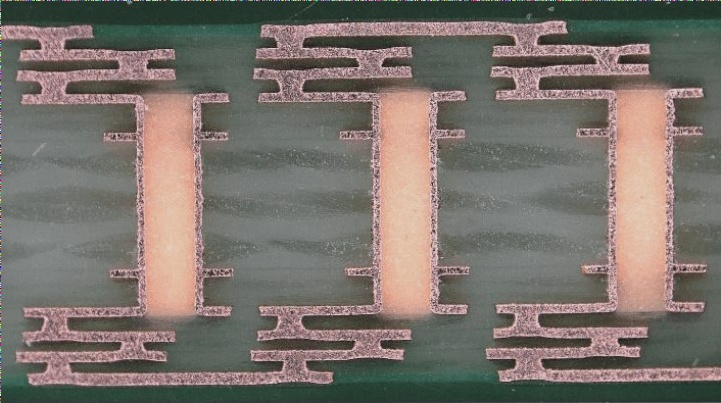
Flexible Zone Design Requirements:
- Utilize tear shapes between thick and thin lines to prevent abrupt expansion or contraction.
- Avoid sharp angles by using rounded corners.
-
Maximizing Pad Size:
When electrical requirements are met, maximize pad size and ensure smooth transitions between bonding pads and conductors.
-
Dimensional Stability:
Maximize copper usage in the design and incorporate solid copper areas in waste regions for dimensional stability.
-
Covering Film Window Design:
- Include manual alignment holes for improved accuracy.
- Design window openings to accommodate glue flow variations.
- Consider special mold designs for small, densely packed window openings.
-
Rigid Deflection Transition Zone:
- Ensure smooth line transitions perpendicular to the bending direction.
- Evenly distribute conductors in the bending area.
- Maximize wire width across the bending area and avoid certain design elements.
-
Flexible Area with Air Gap Requirements:
- Avoid through holes in bending areas.
- Add protective copper wire to sides of the line for reinforcement.
- Design line connections as arcs and increase bending area without affecting assembly.
-
Other Considerations:
Avoid sharing tool holes on flexible boards and reinforce FPCs for improved durability using materials like PI, steel sheet, or FR4.
FPC Reinforcement Options:
- PI Reinforcement: Offers high precision and temperature resistance with various thickness options.
- Steel Sheet Reinforcement: Provides stability but requires manual assembly.
- FR4 Reinforcement: Offers rigidity with controlled tolerances based on thickness.
Each FPC reinforcement type has its advantages and disadvantages, catering to different design requirements.