Preventing Technical Problems When Using Flexible PCBs: Best Practices for International Buyers

Avoiding Delays in Quick-Turn Flexible PCB Orders: Key Challenges and Solutions
When sourcing flexible PCB manufacturers in China for international trade, incomplete design data and technical oversights frequently cause production delays. As a global exporter of high-reliability flex circuits, we’ve identified the most common pitfalls and how to prevent them.
1. Submitting Complete Design Data: The Foundation of Successful Production
How to prepare perfect PCB files for manufacturing: Your data package must include:
- Fully verified Gerber files (RS-274X preferred)
- Detailed mechanical drawings with all specifications
- Complete material stack-up including:
- Copper weight requirements (½ oz vs 1 oz for current capacity)
- Dielectric thickness preferences
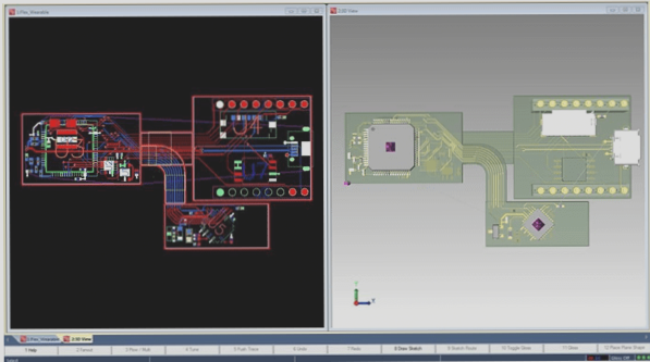
- Flexible vs rigid areas demarcation
“International buyers often underestimate copper weight specifications. For dynamic flex applications, we recommend ½ oz copper for optimal flexibility.”


2. Mechanical Bend Requirements: Designing for Real-World Use
Best flexible PCB design for bend applications requires:
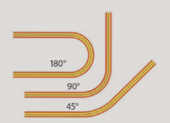
- Clear documentation of all bend locations
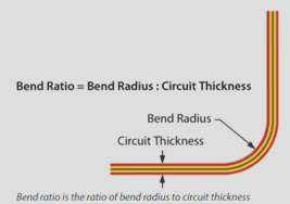
- Accurate radius specifications (minimum bend radius = 6x material thickness)
- Dynamic vs static bend classification
For high-flex PCB applications, consider:
- Neutral axis positioning
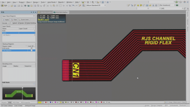
- Conductor routing perpendicular to bend axis
- Reinforcement of transition areas
3. IPC-2223 Compliance: Critical Design Rules for Flexible Circuits

Following IPC flex circuit design standards prevents these common issues:
| Design Element | Best Practice | Risk if Ignored |
|---|---|---|
| Component Areas | Use polyimide stiffeners | Solder joint failure |
| Bend Near Components | Maintain 5mm clearance | Mechanical stress |
| Vias in Flex Zones | Avoid or use tear relief | Crack formation |
| Trace Corners | 45° or curved transitions | Copper fatigue |
4. ZIF Connector Specifications: Ensuring Reliable Interconnections
How to specify ZIF contacts correctly: Your design must include:
- Precise finger location coordinates
- Coverlay opening dimensions (±0.1mm tolerance)
- Stiffener thickness matching connector specs
- Manufacturer part numbers for verification

Advanced Considerations for Export-Quality Flexible PCBs
For international buyers requiring specialty flex circuits, consider these additional specifications:
- EMI shielding: Single/double-sided ground layers
- Adhesive systems: PSA selection for enclosure mounting
- High-temperature materials: For automotive/industrial applications
- Impedance control: Critical for RF applications
Conclusion: Streamlining Your Flexible PCB Procurement Process
By addressing these common flex PCB manufacturing challenges upfront, international buyers can ensure:
- Faster turnaround times (2-3 week standard lead times)
- Higher first-pass yield rates (>98%)
- Reduced total cost of ownership
- Reliable performance in end applications
For complex projects, we recommend early engagement with your PCB manufacturer’s engineering team to review designs before production. This collaborative approach prevents 85% of potential delays in our experience serving global clients.

